• When you click on links to various merchants on this site and make a purchase, this can result in this site earning a commission. Affiliate programs and affiliations include, but are not limited to, the eBay Partner Network.

Ignition Voltage Drop between "start" and "run" | EZ EFI issue

kiltedrunner

Well-Known Member
Local time
6:59 PM
Joined
Nov 17, 2014
Messages
88
Reaction score
44
Location
winnipeg
Hi guys,
I have been trying to track down a way to eliminate the voltage drop between Ignition 1 (run) and ignition 2 (start). The issue is that my FAST display shuts off between these two functions and therefore needs to re-boot everytime I turn the ignition switch from run/start/run.

Does anyone know how to eliminate this issue?
 
were are you testing that ?

THAT'S pretty much normal to original ignition system. Mopar system consist in 2 different circuits to feed the coil in StART and RUN. Both circuits are linked somehow through the ballast resistor

1º stage RUN... coil gets 4.5 to 9 volts through the ballast coming from ign switch blue wire.

2º stage START... coil gets full 12 volts BYPASSING THE BALLAST from ign switch brown wire. This wire being spliced into the "output" side of ballast ( to coil ) will also feed back the rest of the ignition system wiring: regulator, ECU, and even the brake ligh on cluster but on low voltage ( that's the reason why this light dims out while cranking ).

- - - Updated - - -

If you are trying to feed FULL 12 volts on both stages, will need to bypass the ballast, splicing together both ign wires coming from ign switch ( blue and brown ), and then take the power from that splice.

OR, if you still want to keep the stock look of the ballast, remove the resistor from the back of ceramic piece and install a jumper wire on same groove
 
if you take out the ballast, you will need to get a coil that will take full battery & charging voltage, otherwise, yer gonna burn things up
 
Is the main power to the fast unit on a fused batter power and not a switched ignition source? It should have constant 12+ power on one wire and a switched 12+ on another. Did you wire those backwards?
 
Is the main power to the fast unit on a fused batter power and not a switched ignition source? It should have constant 12+ power on one wire and a switched 12+ on another. Did you wire those backwards?


Thanks guys. I no longer have the ballast resistor in my car.

There are actually 2 +12v sources I needed to hook up and they were hooked up as shown in the instructions:
1. Large gauge wire directly from the battery to the ECU
2. Fine pink wire going to the handheld that needs a clean switched +12v power source. FAST suggests not to take from coil.
 
As an alternative, you can take a feed from the IGN1 and from the IGN2 lines separately, and feed each through 2 diodes to a relay coil. In this way, either can power the relay coil through the 2 diodes, and the relay contacts can switch the 12v to your device. However, the one issue may be that when transitioning from IGN1 to 2 and back, there may still be a momentary loss of power.

How do you presently have the switched 12v to the device wired from IGN1 and 2? Do you just have IGN1 and 2 tied together?
 
Is the main power to the fast unit on a fused batter power and not a switched ignition source? It should have constant 12+ power on one wire and a switched 12+ on another. Did you wire those backwards?


That is right. Most all automotive computers use a full 12 volt source to keep everything alive as soon as the switched 12 volts wake the computer up. Ron
 
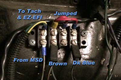
I have the FAST EZ-EFI on my Belvedere, and also an MSD Distributor with the 6AL box. When installing the MSD, I removed the ballast and put a junction block in it's place; I use that block for my Tach trigger and IGN connections.

The FAST Tach trigger is at that block, as well as my Tach signal. The brown and dk. blue wires that connected to the ballast are jumped together now. I've heard people say that there could be starter issues, but I've never had a problem.

The EZ-EFI IGN wire is going to a wire in the dash that was on IGN1 circuit, but since IGN1 and IGN2 are connected at the junction, they both see the same signal during crank and run.

My electrical has been through a lot of transitions, and is now being completely rewired. But initially I started with a Mopar Performance Dist, and carburetors, so when I went to MSD I removed the ballast and put this block in it's place. I used that center red jumper for the electric choke, but going to FAST it was no longer needed.

Since I've had the brown and dk. blue wires jumped like this, I've never had any issues at all, no diodes or relays whatsoever are in the wiring.
junctionstrip.jpg
 
Auto Transport Service
Back
Top