You are using an out of date browser. It may not display this or other websites correctly.
You should upgrade or use an alternative browser.
You should upgrade or use an alternative browser.
K-FRAME STAND
- Thread starter c.moo
- Start date
- Local time
- 11:12 PM
- Joined
- Jan 29, 2018
- Messages
- 21,703
- Reaction score
- 69,123
- Location
- Midland Ontario, Canada
Here's mine.. worked perfect, although I was using a 2 post lift to raise the car off and lower it back on to the K frame assembly.


moparnation74
Well-Known Member
Similar type as above......Bot dollies are from Northern Tool and some 4 x 4 and 2 x4 blocks.......

moparcrazy
Well-Known Member
This one is from a Co. that is no longer in business, Dutch Bro. I happen to have one and it works awesome !!

Last edited:
moparcrazy
Well-Known Member
Here's the full kit, includes the front dolly used not only to lift the car with an engine hoist, but caster's located at the bottom so the car remains mobile

- Local time
- 11:12 PM
- Joined
- Jul 17, 2008
- Messages
- 4,992
- Reaction score
- 3,295
- Location
- Southeastern, PA
- Local time
- 11:12 PM
- Joined
- Jul 17, 2008
- Messages
- 4,992
- Reaction score
- 3,295
- Location
- Southeastern, PA
Cmmopar
Well-Known Member
"
8' - 2"x2" tubing with 3/16" wall
2' - 2 1/2" X 2 1/2" tubing with 3/16" wall
2' - 1 1/2" X 1 1/2" tubing with 1/8" wall
6" - 2 1/2" X 2 1/2" tubing with 1/4" wall
12 - 3/8" X 1" grade 8 bolts
8 - 3/8" nuts
2 - 1/4" X 3/4" bolts
2 - 1/4" nuts
2 - 1/2" X 3 1/2" bolts
4 - 1/2" nuts
2 - 3" HD swivel casters
1 - 3" HD fixed caster
Some 3/16"" plate steel for caster pads, jack pad and two 1 1/2" square pieces for the top of the uprights to hold the 1/2" pins. (Can just weld the casters on)
Cut a piece of 2"X 2" tubing 29 1/2" in lenght and the second one 60" this will make the tee. Next cut four 4 1/2" lengths of the 2 1/2" tubing with 3/16" wall this will be for the adjustable sliders. Cut two 7" lengths of the 1 1/2" tubing this will be for the uprights that hold the pins. Cut one 1 1/2" tubing 5 1/2" in lenght this will be for the rear engine support. Cut two pieces of 1 1/2"X11/2" X 3/16" plate and one 4" X 6" X 3/16" plate.
Now the four pieces of 2 1/2" tubing 4 1/2" long will need
two holes drilled in each one 1" inch from each end and on center. This will be where the 3/8" nuts will be welded for the 3/8" set bolts this will also need to be done on the 5 1/2" piece of the 1 1/2" square tubing for the 1/4" set bolts.Drill a 5/8" hole in the center of the 1 1/2"X1 1/2"X 3/16" then weld the two 1/2" nuts on centered over the hole. This will be for the 1/2" pins, then weld them on one end of the two 7" pieces
of the 1 1/2" tubing with the welded nut inside tubing. Once the ends are welded on then weld the 7" pieces to two of the 2 1/2" tubing that's 4 1/2" long place them 3/4"
from the end (refer to the pics) also the set bolts will be at the bottom. The other two pieces of 2 1/2" tubing 4 1/2"
long wil be for the trans jack and rear engine support.
Weld the 4"x6" 3/16" plate to one of them with the set bolts to the bottom also this plate will need to be offset 2 3/8" to the right from center of plate the 6" lenght this is due to the offset of the engine in relation to the k frame and frame rails. the 1 1/2" tubing 5 1/2" welds to last piece of 2 1/2" tubing for the rear engine support. I have not finished this part yet just waiting to get the engine and tranny on to see what's needed. If you want to be able to disassemble it for storage cut the tee on the long piece 4"
back from the short side of the tee and use the 2 1/2 tubing that's 6" long to couple it together. Drill and tap
two 3/8" holes on each end of the coupling to secure the tee together. Then install casters however you choose.
Then stencil "poor boy" on it and if you decide to build and sell them give me some royalty money.
 "
"https://www.forabodiesonly.com/mopar/threads/built-me-a-new-tool.350813/
- Local time
- 10:12 PM
- Joined
- Feb 20, 2012
- Messages
- 74,775
- Reaction score
- 287,214
- Location
- New Hampster
Must have been interesting finagling the shifter lever in the hole in the floor while lowering it. 

- Local time
- 11:12 PM
- Joined
- Jan 29, 2018
- Messages
- 21,703
- Reaction score
- 69,123
- Location
- Midland Ontario, Canada
Probably could have put it up in 3rd... but it's a slip out Pro comp!

c.moo
Well-Known Member
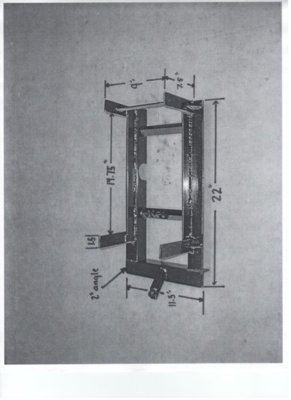
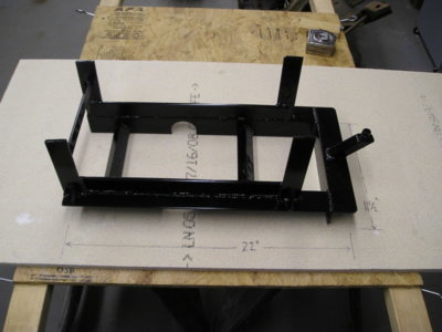
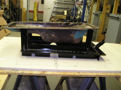
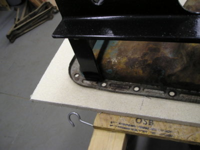
View attachment 602058 View attachment 602057 One of the best designs and material/plans write ups for k frame dolly that I have seen. Rods on front posts of dolly fit factory holes in bottom of kframe leaving all k frame bolt holes open for easy installation. Jack in rear is nice design..Thanks to cudascott from forabodiesonly..
"
8' - 2"x2" tubing with 3/16" wall
2' - 2 1/2" X 2 1/2" tubing with 3/16" wall
2' - 1 1/2" X 1 1/2" tubing with 1/8" wall
6" - 2 1/2" X 2 1/2" tubing with 1/4" wall
12 - 3/8" X 1" grade 8 bolts
8 - 3/8" nuts
2 - 1/4" X 3/4" bolts
2 - 1/4" nuts
2 - 1/2" X 3 1/2" bolts
4 - 1/2" nuts
2 - 3" HD swivel casters
1 - 3" HD fixed caster
Some 3/16"" plate steel for caster pads, jack pad and two 1 1/2" square pieces for the top of the uprights to hold the 1/2" pins. (Can just weld the casters on)
Cut a piece of 2"X 2" tubing 29 1/2" in lenght and the second one 60" this will make the tee. Next cut four 4 1/2" lengths of the 2 1/2" tubing with 3/16" wall this will be for the adjustable sliders. Cut two 7" lengths of the 1 1/2" tubing this will be for the uprights that hold the pins. Cut one 1 1/2" tubing 5 1/2" in lenght this will be for the rear engine support. Cut two pieces of 1 1/2"X11/2" X 3/16" plate and one 4" X 6" X 3/16" plate.
Now the four pieces of 2 1/2" tubing 4 1/2" long will need
two holes drilled in each one 1" inch from each end and on center. This will be where the 3/8" nuts will be welded for the 3/8" set bolts this will also need to be done on the 5 1/2" piece of the 1 1/2" square tubing for the 1/4" set bolts.Drill a 5/8" hole in the center of the 1 1/2"X1 1/2"X 3/16" then weld the two 1/2" nuts on centered over the hole. This will be for the 1/2" pins, then weld them on one end of the two 7" pieces
of the 1 1/2" tubing with the welded nut inside tubing. Once the ends are welded on then weld the 7" pieces to two of the 2 1/2" tubing that's 4 1/2" long place them 3/4"
from the end (refer to the pics) also the set bolts will be at the bottom. The other two pieces of 2 1/2" tubing 4 1/2"
long wil be for the trans jack and rear engine support.
Weld the 4"x6" 3/16" plate to one of them with the set bolts to the bottom also this plate will need to be offset 2 3/8" to the right from center of plate the 6" lenght this is due to the offset of the engine in relation to the k frame and frame rails. the 1 1/2" tubing 5 1/2" welds to last piece of 2 1/2" tubing for the rear engine support. I have not finished this part yet just waiting to get the engine and tranny on to see what's needed. If you want to be able to disassemble it for storage cut the tee on the long piece 4"
back from the short side of the tee and use the 2 1/2 tubing that's 6" long to couple it together. Drill and tap
two 3/8" holes on each end of the coupling to secure the tee together. Then install casters however you choose.
Then stencil "poor boy" on it and if you decide to build and sell them give me some royalty money."
https://www.forabodiesonly.com/mopar/threads/built-me-a-new-tool.350813/
c.moo
Well-Known Member
It said use two 1/2 pins for holes in k-member , not mounting holes . I have 2 holes ,not 1/2 inch in k-member , the holes i have in my is 5/16 and 7 7/8 from center to center . If drill these out bigger will be hitting side of k -member and 7 7/8 seems not far apart to hold load . What am i missing here ? Thanks
70BeepBeep
Well-Known Member
Mocajava
Well-Known Member
SoCal440GTX
Well-Known Member
I had 2 of those built, but haven't used one yet.Try this.. this is the one I built.
Now I'd like plans for this...
SureGrip
Well-Known Member
That's slicker than goose crap. Nice!Here's the full kit, includes the front dolly used not only to lift the car with an engine hoist, but caster's located at the bottom so the car remains mobile
View attachment 600756
skicker
Well-Known Member
- Local time
- 11:12 PM
- Joined
- Dec 15, 2011
- Messages
- 1,454
- Reaction score
- 3,710
- Location
- Cumberland, Maryland
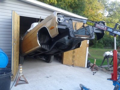
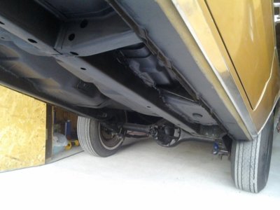
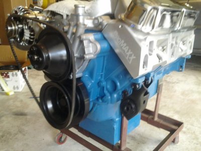
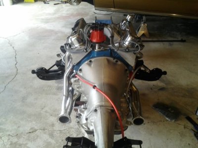
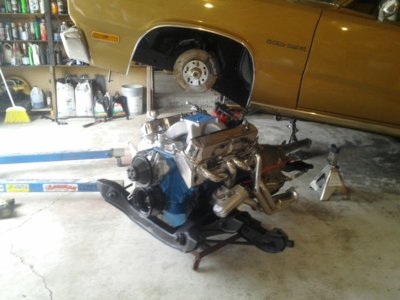
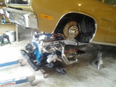
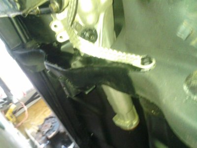
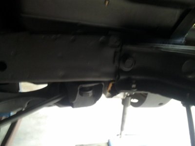
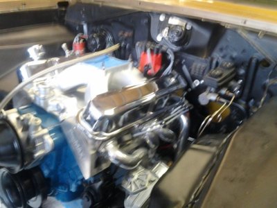
Mine seems to work very well...
You don't have to have the car very high in the air as the rear tires stay on the ground.
I use an engine crane on a piece of 2x2 box tubing between the frame rails to lift the car up.
Slide the engine...trans and K frame in and lower it down.
No removing the hood or grill or front bumper.
Connect the 4 transmission cross-member bolts first and then lower it down a little more to attach the K frame.
It takes maybe 15 minutes from the time you lift the car till it's back on the jack stands with the crane removed...
Attaching the 2x2 tubing and running the crane in under the upper rad support makes it great for lifting the car very high to clean and paint.


Snook
Well-Known Member
- Local time
- 11:12 PM
- Joined
- Jan 15, 2020
- Messages
- 1,233
- Reaction score
- 2,133
- Location
- Okeechobee, Florida
Ceedawg
Well-Known Member
This is what I’ll make, where do the pins go in? I’ll also make a cradle for that sizzor jack to fit around trans tail housingView attachment 602058 View attachment 602057 One of the best designs and material/plans write ups for k frame dolly that I have seen. Rods on front posts of dolly fit factory holes in bottom of kframe leaving all k frame bolt holes open for easy installation. Jack in rear is nice design..Thanks to cudascott from forabodiesonly..
"
8' - 2"x2" tubing with 3/16" wall
2' - 2 1/2" X 2 1/2" tubing with 3/16" wall
2' - 1 1/2" X 1 1/2" tubing with 1/8" wall
6" - 2 1/2" X 2 1/2" tubing with 1/4" wall
12 - 3/8" X 1" grade 8 bolts
8 - 3/8" nuts
2 - 1/4" X 3/4" bolts
2 - 1/4" nuts
2 - 1/2" X 3 1/2" bolts
4 - 1/2" nuts
2 - 3" HD swivel casters
1 - 3" HD fixed caster
Some 3/16"" plate steel for caster pads, jack pad and two 1 1/2" square pieces for the top of the uprights to hold the 1/2" pins. (Can just weld the casters on)
Cut a piece of 2"X 2" tubing 29 1/2" in lenght and the second one 60" this will make the tee. Next cut four 4 1/2" lengths of the 2 1/2" tubing with 3/16" wall this will be for the adjustable sliders. Cut two 7" lengths of the 1 1/2" tubing this will be for the uprights that hold the pins. Cut one 1 1/2" tubing 5 1/2" in lenght this will be for the rear engine support. Cut two pieces of 1 1/2"X11/2" X 3/16" plate and one 4" X 6" X 3/16" plate.
Now the four pieces of 2 1/2" tubing 4 1/2" long will need
two holes drilled in each one 1" inch from each end and on center. This will be where the 3/8" nuts will be welded for the 3/8" set bolts this will also need to be done on the 5 1/2" piece of the 1 1/2" square tubing for the 1/4" set bolts.Drill a 5/8" hole in the center of the 1 1/2"X1 1/2"X 3/16" then weld the two 1/2" nuts on centered over the hole. This will be for the 1/2" pins, then weld them on one end of the two 7" pieces
of the 1 1/2" tubing with the welded nut inside tubing. Once the ends are welded on then weld the 7" pieces to two of the 2 1/2" tubing that's 4 1/2" long place them 3/4"
from the end (refer to the pics) also the set bolts will be at the bottom. The other two pieces of 2 1/2" tubing 4 1/2"
long wil be for the trans jack and rear engine support.
Weld the 4"x6" 3/16" plate to one of them with the set bolts to the bottom also this plate will need to be offset 2 3/8" to the right from center of plate the 6" lenght this is due to the offset of the engine in relation to the k frame and frame rails. the 1 1/2" tubing 5 1/2" welds to last piece of 2 1/2" tubing for the rear engine support. I have not finished this part yet just waiting to get the engine and tranny on to see what's needed. If you want to be able to disassemble it for storage cut the tee on the long piece 4"
back from the short side of the tee and use the 2 1/2 tubing that's 6" long to couple it together. Drill and tap
two 3/8" holes on each end of the coupling to secure the tee together. Then install casters however you choose.
Then stencil "poor boy" on it and if you decide to build and sell them give me some royalty money."
https://www.forabodiesonly.com/mopar/threads/built-me-a-new-tool.350813/
Similar threads
- Replies
- 8
- Views
- 2K
- Replies
- 12
- Views
- 1K

