• When you click on links to various merchants on this site and make a purchase, this can result in this site earning a commission. Affiliate programs and affiliations include, but are not limited to, the eBay Partner Network.

Temp Gauge / Temperature Gauge

Grabinov911

Well-Known Member
Local time
6:31 AM
Joined
Jan 27, 2012
Messages
558
Reaction score
245
Location
Southern California
Ok guys. Show me your skills!

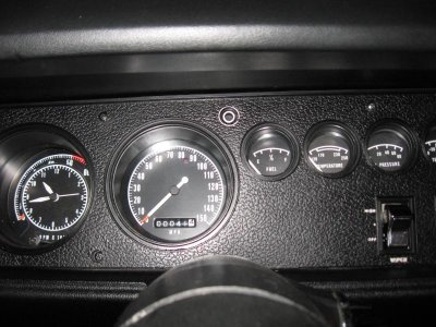
1970 Roadrunner, 383, Rallye Dash.

My fuel gauge works. My oil pressure gauge works. My Temperature Gauge doesn't.

I have replaced the sender twice but it makes no difference. With the ignition on, If I ground the temperature gauge sender wire (at the engine compartment end) the gauge moves slowly to HOT like it should. But the gauge doesn't work. I have the car hot enough to open the 180 degree thermostat, so I should see SOMETHING on the gauge.

What could be wrong? What to check next?
 
The problem might be the voltage limiter on the back of the dash pc board.
 
just because you replaced the sender DOES NOT MEAN ITS GOOD. i have the same car as you and i just rebuild my entire dash last month.

if the limiter was bad none of the gauges would work( except alt gauge) lets test it anyway.....

test the limiter...heres how: (make sure key is off before you begin)

1.get a test light without a battery in it..
2. put the ground clip on the battery negative(-)
3.either probe the sending unit wire with pointy part of the test light....OR... manipulate the sending wire so that you have BOTH sending unit wire AND pointy part of the test light touching the sending unit threads where the wire goes at the same time.
4. turn on key
5. your test light should pulsate dim to bright.
6. if it pulsates...ITS WORKING......if not....GET ONE THAT WORKS. (dash will have to come out to replace.)


test the sending unit ...DO NOT WRAP WHITE TEFLON TAPE OR ANYTHING AROUND THE MOUNTING THREADS... this is the ground and may be your problem)

1. get a test light WITH a battery in it ( please make sure it works or you'll drive yourself crazy)
2. with sending unit in the car...put the ground clip of the test light to a GOOD KNOWN GROUND ( like the battery or engine block)
3. take off the sending unit wire and put the test light pointy part on there where sending unit wire goes.
4. the test light should light dim when cold and brighter as it gets hotter .

test your other sending units this way too OUT OF THE CAR:

ground the test light clip to the threads on the unit.....pointy part on the stem threads...light should glow (battery powered test light)

the voltage limiter on the circuit board in the dash cuts the voltage from 12v to 5v. the gauges run on this 5v as well as the 3 twist in bulbs ( on the circuit board) that illuminate the small gauges.
 
TPO,

Genius. :headbang:

I am guessing the voltage limiter is the cylinder looking object on the back of the dash? I have a Power Probe so i'll run the tests you suggest. If the limiter is bad i'm thinking the smart thing to do is to replace the old school limiter with a solid state type.

MAN do I hate taking out the dash on this car! Oh well. One more time won't kill me. Thanks TPO!

the limiter is a rectangle looking thing on the back of dash cluster. when i rebuilt my dash , i got a new circuit board with solid state limiter from charger speciaties. it was 126.00 but well worth it! you can also eliminate the radio surpressor ( thats the cylinder looking thing)

good luck and let me know if you need any more help
 
heres a pic of my old circuit board. the voltage limiter is the metal box on the far right lower. if you are going to remove your dash again. ...now is a good time to clean up everything so this does not happen in the future.

clean the gauge mounting studs (rust and corrosion)
clean the circuit board copper leads ( remove the tarnish with 0000 steel wool..VERY LIGHTLY )
MAKE SURE ALL GROUNDS ARE CLEAN (very important)


i still have all my guages and speedo...i sold the tic toc tach. if you need any of them ill let em go relatively cheap..( they all worked but i couldnt stand looking at the yellowed out gauges and thats why i replaced them)
speedo has 72,999,9 on it
 

Attachments

  • 004.jpg
    004.jpg
    45.8 KB · Views: 658
just a pic of the rebuilt dash to make ya drool a bit...LOL.

i painted the tips of the tach and speedo needles orange to make them easier to see, these dashes are not all that brightly lit at night and that really makes it easy to see when the dash is lit up. i was going to paint the tips of all the needles but opted out of that:headbang:
 

Attachments

  • roadrunner rallye wheels 005.jpg
    roadrunner rallye wheels 005.jpg
    81.5 KB · Views: 379
Thanks again. I actually did exactly as you suggest last time I had the dash out. I'm not much for carbueretors but i can do D.C. Electrical pretty well! I cleaned everything up, etc but couldnt get everything to work perfectly, so i gave up and moved on to other projects.

The more I think about it the more I believe it's the voltage regulator. The small lights at that end of the dash are not working either, and did once. I had a minor Alternator gauge catastrophe at one point (I have since wired around it) and my guess is that I burned the regulator at that time, but I thought when the regulator failed the circuit went to 12 volts not to 0 volts. Hmmm...

I actually started all this when I added a tic toc tach to the instrument panel. The empty pod was there but the car had no tach from the factory. I have actually been considering building an entire new gauge cluster for the car using modern gauges, and would have done it already if I could figure out a good way to replace the headlight and dimmer switches! Aftermarket gauges are easy to find, but aftermarket headlight switches???

I had a good conversation with a guy named Tom at RT Engineering once and I may purchase one of their "IVR4" voltage regulators to replace the factory one. Standby this channel...


I would bet just about anything that when you had your incident with the ammeter that you scorched a copper lead/path on the circuit board. That explains everything in my mind. Lights and temp gauge.
 
i doubt its the voltage regulator.......you said all gauges but temp are working, and the fuel and oil gauge WONT work with a shot volt reg. theyre all on the same circuit board and all run on the same 5 volts
I would bet just about anything that when you had your incident with the ammeter that you scorched a copper lead/path on the circuit board. That explains everything in my mind. Lights and temp gauge. the circuit board is delicate and Brian RR might have some validity.

ALSO:..you confirmed that the temp gauge "PEGS" when grounded out....so the circuit board might be ok.... heres my guess:

you have a bad gauge and is only registering the low resistance (pegs when grounded).... im out of ideas...we pretty much eliminated everything else!

check the pins on the circuit board and clean them.....im runnin out of ideas
 
Test Results

I followed TPO's test regimen as prescribed above:

Test the Limiter: With the key on and a test light connected in series between the temperature sending unit wire and a solid ground, the light pulsates. A volt meter hooked in the same fashion shows fluctuating voltages between battery voltage and 0. THE LIMITER APPEARS TO BE FUNCTIONING.

Test the Sending Unit: A powered test light placed in series between the sending unit connector and a solid ground (designed to test the resistance of the sending unit under changing temperature conditions) shows a brighter light when the engine is hot. Dimmer when the engine is cold. An ohm-meter connected in the same fashion shows the same; increased resistance at cold temperatures (up to 350 ohms), decreased resistance at high temperatures (down to 75 ohms) with a smooth change between. Resistance varies smoothly and inversely with temperature. THE SENDING UNIT APPEARS TO BE FUNCTIONING.

Further Tests

With the sending unit connector grounded directly to a solid ground and the ignition key on, voltage regulated by the voltage regulator on the dashboard passes directly to the gauge with no resistance. Under these conditions the gauge moves all the way to the hot limit of the gauge. WHEN THE GAUGE IS GROUNDED WITH NO RESISTANCE, KEY ON, 12 VOLT POWER FROM THE SENDING UNIT LEAD PROPERLY PASSES TO THE GAUGE.

I disconnected the battery completely and replaced it with a 6 volt battery, then re-ran the test above. Same result. Good gauge Function. The gauge clearly works fine with only the 6 Volts (5 really)that it is supposed to get from the voltage regulator.

Tested continuity between the sending unit wire and the sending unit body. Good continuity. Good connection between sending unit and sending unit wire. 0 resistance.

Tested continuity between sending unit body and ground. Good connection between sending unit body and ground. 0 resistance.

I cannot even imagine anything else to test. All of the parts function separately, but the system does not. :thinker:
 
Auto Transport Service
Back
Top