• When you click on links to various merchants on this site and make a purchase, this can result in this site earning a commission. Affiliate programs and affiliations include, but are not limited to, the eBay Partner Network.

Troubleshooting the temp gauge circuit, see lots of suggestions, but no real answers.

idrivemopar

Well-Known Member
Local time
8:18 AM
Joined
Apr 30, 2012
Messages
3,698
Reaction score
2,706
Location
Colorado
So, now, I did do a search, and apologies if I missed it completely, but I have a general question regarding troubleshooting the temperature gauge/sensor circuit. I have seen several threads on this subject over the years, and was wondering this;

Is there any more concrete method to determining what the problem is rather then just switching sensors, or checking grounds, replacing voltage limiter, or replacing gauge, etc?

For instance;

1. Does anyone know what the resistance curve is for the sensor from cold to overheat, certainly, there must be some information somewhere.
2. Concerning the gauge, and I have looked in service manuals, owners manuals, and no information on this, but what's the general consensus (I know this varies depending on thermostat installed), but where should the gauge needle be for normal operating temperature, in the middle, slightly above or below the middle of the gauge?
3. Anyone know how to properly troubleshoot the voltage limiter?
4. And where does one find the newer solid state limiters, I see RTE, are they the go to source for these?


Would love to see a sticky on this subject!!!!!!!!
 
1) Standard Brand TS17. Call for tech support and ask for a white paper on the sensor. (I think it is going overkill, if you don't like the sensor, just replace it. I am an engineer also, and understand the desire to know the resistance at a certain temperature. A resistor is a linear device, so it will be an approximate straight line and not a curve)
2) My gauge was usually at mid-scale for a normal reading.
3) With 12vdc applied to the proper terminals, you should get approximately 5vdc out.
4) I have never used one, but I probably would if I get the need again.
 
I know this doesn't directly answer your question, but it seems to me that you are trying to calibrate your OEM gauge to a degree that outsteps its intended precision. I choose to run an aftermarket gauge, but for a short time I ran both the factory and the aftermarket, with both temp senders literally within inches of each other. In my experience, top dead center of that gauge is right in 180*, and the farthest limit of my factory gauge (for me) was about 220 or so (my car ran HOT when I first bought it). In the end I chose to go aftermarket and leave my factory gauge dead because I just needed more 'data' (I'm also an engineer).
 
I also have an aftermarket. And, carry a thermal laser temp gun to be sure.
 
Hey 69bee, everyone else, I appreciate the feedback, and I certainly know these things were not meant to have an accuracy within a few degrees of reality, and I'm not trying to calibrate it, but I just wanted to get a better understanding of the relationship between the gauge and the sensor, that is all, trust me, I have done a lot of replace this or that troubleshooting over the years, I guess maybe its just my curiosity has gotten the best of me and I like to know details on stuff you know!!! LOL Cheers!
 
So, now, I did do a search, and apologies if I missed it completely, but I have a general question regarding troubleshooting the temperature gauge/sensor circuit. I have seen several threads on this subject over the years, and was wondering this;

Is there any more concrete method to determining what the problem is rather then just switching sensors, or checking grounds, replacing voltage limiter, or replacing gauge, etc?

For instance;

1. Does anyone know what the resistance curve is for the sensor from cold to overheat, certainly, there must be some information somewhere. From what metering I've done it's simply 0-100 ohms using a lighter to heat the sensor casing not much more to it than that.
2. Concerning the gauge, and I have looked in service manuals, owners manuals, and no information on this, but what's the general consensus (I know this varies depending on thermostat installed), but where should the gauge needle be for normal operating temperature, in the middle, slightly above or below the middle of the gauge? I use both factory and mechanical and when my gauge reads 180° the factory one is just past halfway.
3. Anyone know how to properly troubleshoot the voltage limiter? Never had to on my old one but could only imagine how simple it is, 12vdc in, ground and 5vdc out simply find where the source is and test it there and then ground which would leave the 5vdc if you have them all then its good if not well..
4. And where does one find the newer solid state limiters, I see RTE, are they the go to source for these? Yes http://www.ebay.com/itm/Mopar-68-69...NEW-/400943070324?hash=item5d5a11bc74&vxp=mtr


Would love to see a sticky on this subject!!!!!!!!


Hope this helps some. As you know like the fuel gauge the sensor uses resistance to vary the 5vdc to the gauge you could rig up a test subject using the factory cluster and an old sensor connected to the factory wiring and chassis ground.
 
Readings I came up with - '69 Rallye dash


Fuel Gauge - E 1/8 1/4 3/8 1/2 5/8 3/4 7/8 F

Resistance - 68.0 49.0 40.0 31.0 25.5 21.0 17.5 14.0 12.0 Ohms


Temp Gauge - 120° F 170° F Center 230° F 250° F

Resistance - 68.0 34.0 21.0 15.0 12.0 Ohms


Oil Pressure, PSI - 0 10 20 30 40 50 60 70 80

Resistance - 68.0 40.0 31.0 25.0 21.0 18.5 16.0 14.0 12.0 Ohms
 
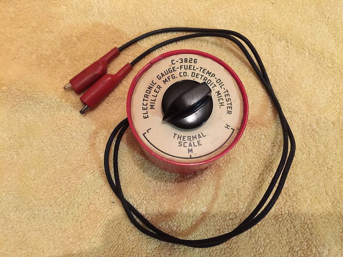
Remove the sensor from the car and attach an ohmeter to the body side and the terminal. Place it in cool water so only the bulb (and maybe part of the threads) are immersed. Hang a thermometer in the pot but not touching the sides. Register your first reading on the ohm meter with the water cold and start to warm the water by whatever means you can. As the temp goes up note the water temp and the corresponding resistance until full boil. You can do this also with voltage using 12v (low amperage) and the VOM meter set to 12v DC. Note your temps and voltage passing through the sensor. Now connect a power source to the gauge and starting at 0 volts increase until the gauge reads far right. You can do this by stacking flashlight batteries in a cardboard tube from wax paper etc.12 volts may not be required to achieve this so you have to keep track of the input voltage to the gauge terminals and remember that the gauge is polarity dependent.Compare readings for temp, resistance, and volts and you'll discover where the needle rests for varying temp signals sent by the sender.
 
That's pretty sweet, I could build one of those.

- - - Updated - - -

Looks like someone has already doNE it over on a-bodies. http://www.forabodiesonly.com/mopar/showthread.php?t=179517 I know what I'm doing next!

Thas me ramblin onwards. Bear in mind that the reason those particular resistors "got used" is that this was a "junk box" project and because of the switch I used.

SOMEWHERE there IS a curve for the temp thermistor, I don't know where. But the gauge units are not as accurate as the thermistor, LOL

The other problem "is" that there "is" that is "can be" other problems.

Poor connections at the PC board harness. Poor connections at the IVR "connector" socket. Poor connections at the guage studs "fake nuts." And of course wiring connections, such as the bulkhead connector

the IVR can be out of calibration.

The temp / fuel gauge units themselves can be out of cal, and "how old" again are these old girls?

The BIG issue over on FABO seems to generally be fuel gauge accuracy, and THAT seems mostly to be in "repop" fuel senders. Someone over there found a PROGRAMMABLE gauge calibrator. I recently ordered one, have not received it, yet

This thread

http://www.forabodiesonly.com/mopar/showthread.php?t=264543

which lead to this unit here

http://technoversions.com/MeterMatchHome.html

- - - Updated - - -

http://technoversions.com/MeterMatchHome.html
 
Thanks 440roadrunner, very useful info, I am kind of a hobby electronics guy, and have a ton of parts laying around, so it shouldn't really cost me anything to build that tester. I have heard about the problems with the after market fuel pickups as well, but I must have gotten lucky, as the one I got is pretty close to my original, and my other gauges (oil and temp) seem to work fine, but I always wanted to know where they should be, especially after my restoration was completed with all new wiring and sensors, and by the info provided here, they seem to be right where they should be, well, as close as they can be to when it was new I suppose.
 
Auto Transport Service
Back
Top