These are my notes. I may have changed a thing or two since.
Original fuse box has 5 fuses:
1) Dash lights
2) To light switch for interior lights and to hazard flasher/stop light switch
3) Lighter
4) Heater
5) Radio
Bought Painless 70207 fuse block, 7 circuits (3 Constant, 4 Ignition), 20amp fuses, circuit breaker included.
Removed old fuse box, mounted Painless in same spot, fits perfect.
Ammeter/Alternator Charge Wire
1) Ammeter and wiring with welded splice eliminated entirely by just bypassing it, left in place within the dash harness.
2) New Denso 60 amp Alternator.
3) New Alternator charge wire to Starter Relay – 8-gauge wire with a 6 inch 12-gauge fusible link.
4) New Sense wire with inline fuse from Alternator to Starter Relay.
Headlight Relay Kit
1) Bought from a FABO/FBBO member, crackedback I think.
2) Relays and fuses can be mounted anywhere, under the battery, radiator support.
3) 2 power wires can be routed across the firewall to the Alternator stud, or in front of the radiator support with the headlight harness.
4) Eliminates power going directly to headlight switch then back out to headlights.
Positive Junction Block mounted under dash, made a small bracket.
1) Connected the ‘Start’ wire (Brown).
2) Connected the ‘Run’ wire (Blue Tracer).
3) New wire to positive on coil.
4) New wire to a voltmeter.
5) Tach power.
Painless Fuse Box
3 Constant
1) Wire directly to light switch (B1, replaces BLK-TR). Light Switch was not originally fused.
2) Wire directly to ignition switch (replaces RED wire). Ignition switch was not originally fused.
3) Wire to pink/pink splice where fuse box was (to light switch for interior lights and to hazard flasher/stop light switch).
4 Ignition
1) Wire directly to heater switch (BLACK-TR).
2) Wire directly to new alternator.
3) Wire directly to aftermarket radio.
4) Extra.
That leaves 3 wires where the old fuse box was:
1) BLACK – into the fuse box – comes from the ignition, goes to a welded splice, then out to the Directional Flasher, Gauges, and fuse box. It is an Ignition power source, so I connected it to the Painless Pink wire.
2) TAN – into the fuse box, it is the feed from the Light Switch to adjust the Instrument Lights.
3) ORANGE – out from fuse box, it is the power to the Instrument Lights
4) TAN and ORANGE – inline fuse holder with a 10amp, spliced them together, zip tied to the side of the Painless.
Notes
1) Distributor power from positive on coil.
2) Original ORANGE wire for radio lights used for lights on Tach/Accessory Gauges.
3) Aftermarket radio came with fused constant power from battery, but I don't think I ran it to the battery, I forget where I picked up constant power, only for memory. I bought a Pioneer blue tooth deck, no cd, half the size, a quarter the weight, battery has been disconnected all winter and it kept the preset radio stations, so maybe I didn't need it.
4) When running wires directly to original plastic connectors, used terminals that fit and lock in.
5) Original harness runs on driver side inner fender. Removed wiring from engine on passenger side and routed on passenger inner fender. Factory holes already there, used factory harness clips. No wires on engine.
6) Use harness tape, not electrical tape, factory connectors, regular connectors, heat shrink, heat gun, good crimpers, etc. Bought all in bulk, cheaper and mistakes/changes don't leave you with not enough of this or that to continue.
7) New instrument circuit boards and lights. Made a small harness to ground every light, from the back of the instrument cluster to the dash.
8) Negative hub mounted on firewall next to battery.
9) Replaced headlights with H4 and new housings.
10) Replaced interior bulbs with LEDs.
11) Replaced taillight and reverse bulbs with ones for a Honda, more $ but last decades.
12) Replaced both flashers with the NAPA solid state one, it’s like $13 but well worth it. Directionals work awesome!
13) See Daniel Stern Lighting for bulb and flasher info.
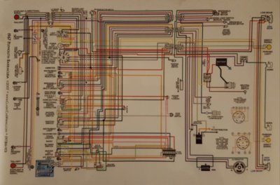
Pic of my original wiring diagram, which is a large laminated color copy, I think I got it on ebay, and it was a great tool.
My harnesses were all new or in excellent shape before I did this, so leaving existing wiring was a good choice for me, plus all the major stuff was replaced or eliminated.
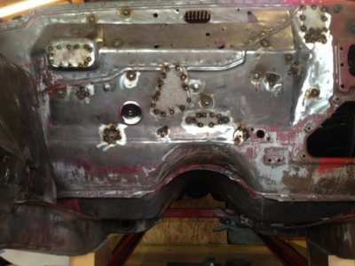
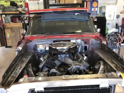
Other pics are during the re-wire, not the final product, but it might help.
I'll be doing the same to my 62. I might even have to build a harness from scratch, but once you get the correct connectors for the factory plastic plugs it's so easy. Got mine from Summit.
Also, I somehow had extra black and red vacuum port block of things, so I put them on the studs of my pos and neg junction blocks, and one on my alternator stud.
When replacing or running a new wire to the engine bay, I ran it straight thru the bulkhead connector, no wire connectors. The only original connectors at the bulkhead are for the headlights, wipers, and reverse lights.


