• When you click on links to various merchants on this site and make a purchase, this can result in this site earning a commission. Affiliate programs and affiliations include, but are not limited to, the eBay Partner Network.

Holley Sniper installation - a Guide for beginners

kiwigtx

Henchman #4 and Jack-Stand Racer #2
Staff member
FBBO Gold Member
Local time
11:43 AM
Joined
Jun 12, 2012
Messages
34,452
Reaction score
91,526
Location
NZ - just short of the South Pole
...or a Guide for Dummies :D

Please feel free to post your experiences...and Tips on How to...or How NOT to here

Useful information only please.

I'll start with my number 1 rule....

"Read the manual and installations supplied....thoroughly. Then read them again. Handle all items to familiarize yourself with parts...then read the instructions again." :thumbsup:
 
Make sure your supply line and return line are hooked up correctly. I made those mistake, made the change and fired right up.:BangHead:
 
My thoughts on that are that the excess fuel flowing through the Sniper module actually provide a cooling effect as fuel is constantly passing the heated up areas of the throttle body.

There is a diagram on the Holley site showing a bypass/regulator alternative in the supply line, but this WILL NOT work. Return lines must originate from the Sniper unit. I found this out the hard way. Problem solved with another bunch of AN fittings and more hose.

Make sure you get a quality fuel pump also...in-tank is best, but as I ended up making a custom tank, it wasn't an option at the time. In-line pumps on the chassis rail make noise prior to start-up, but a healthy engine drowns out that 'white noise'. :)
 
Make sure your supply line and return line are hooked up correctly. I made those mistake, made the change and fired right up.:BangHead:

Rule 1: RTFM. The manual says to cycle the fuel pump three times to clear any stuff in the feed line. Use a containers for each line and you'll figure out which one is which real quick, because the feed will have two gallons in it after the fuel pump cycles three times.

My thoughts on that are that the excess fuel flowing through the Sniper module actually provide a cooling effect as fuel is constantly passing the heated up areas of the throttle body.

There is a diagram on the Holley site showing a bypass/regulator alternative in the supply line, but this WILL NOT work. Return lines must originate from the Sniper unit. I found this out the hard way. Problem solved with another bunch of AN fittings and more hose.

Make sure you get a quality fuel pump also...in-tank is best, but as I ended up making a custom tank, it wasn't an option at the time. In-line pumps on the chassis rail make noise prior to start-up, but a healthy engine drowns out that 'white noise'. :)

You're 100% correct. The fuel will be cooler if you run a return line. The manual says there should be no more that 3 psi of resistance on the line. There's two type of fueling systems. Return and 'dead head' (returnless). Return is always the best but is more difficult to install.

In dead headed system, the pump will reach a pressure then stall. The motor will fight against itself and the pressure, which means it won't last as long. Another huge down side is the fuel pressure will also drop a ton in a dead headed system when you punch the gas. A returned system is better able to meet the demand of the system.

Fuel pumps:

You can run an external pump, but an in-tank pump is best. There's a reason why every car manufacture runs an intake pump. For me it was the questions of "Where am I going to mount this thing? How am I going to do the hook up? And damn my exhaust runs very close to the fuel pick up!"

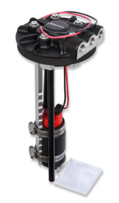
For intank pump, there many different options to choose from. The most common are:

Tanks Inc
prd_227.jpg

Aero Equip
18689.jpg


Holley Sniper
19-350-v118194.jpg

Holley EFI.
12-13718124.jpg


I went with the Holley 12-136, 255 LPH, with the HydroMat. The Hydro Mat is no joke! I have twice ran my tank to completely empty and still made it to the gas station with only a slight drop in pressure. I'm talking 15.9 gallons in a 16 gallon tank!

I'll talk about mounting options in my next post.
 
Last edited:
I would have gone in-tank...however I had already ordered a swag of parts, then realised my gas tank was not up the job. Serious time issues and pressures. :(
 
I'm going to chime in, even though I have FiTech.

In tank, make sure the in tank line is not rubber, even if it is rated for efi. It will soften when submerged. My Hyperfuel pump came with efi rubber and only 1 clamp, designed that way. A trip to napa for correct line and clamps resolved it. Otherwise awesome pump, an fittings on it, ready to go.

PTFE fuel line, braided stainless covered teflon, incredibly easy to assemble fittings and much less time and $ spent on install.

I didn't want to run returnless, and with a dual quad a return was slightly more involved. I ended up using a 'corvette' regulator/filter. I learned about it on fabo as others have used it with success, including gm. AN fittings, mounts on the rear frame rail, easy access, provides the required 58 psi.

Mount a fuel pressure gauge somewhere visible.

EFI is great, but when diagnosing issues don't forget to use the kiss principle. Sometimes the issue is outside of the efi system, people forget what they already know, and blame the efi, self included.

Get a new tank set up for efi. A clean, new tank saves time, they are not expensive, and have nice features, flat area on top, baffle inside, sending unit mount, vent port. You spent all this $ on the efi, get the tank.

Keep your tank at least 1/4 full for an in tank pump. It needs the fuel as there is fuel in the line, the return, the filter, the throttle body, etc. My pump runs 100psi+ unregulated, with little to no fuel to pump bad things will happen. Also my understanding is it keeps the pump cool.

Upgrade your alternator and electrical. I did the denso alt, fuse box, no ammeter, ground and power hubs, etc.

Oh yeah, and ground everything to a common ground. My tank, pump, sending unit, alternator, etc, all grounded to a hub, to the battery.

RPM noise, or similar. EFI can be affected by electrical noise, especially from the coil and distributor power wires. Shielding the trigger wire from the key to the ecu solved it for me.
 
Rule 1: RTFM. The manual says to cycle the fuel pump three times to clear any stuff in the feed line. Use a containers for each line and you'll figure out which one is which real quick, because the feed will have two gallons in it after the fuel pump cycles three times.


You're 100% correct. The fuel will be cooler if you run a return line. The manual says there should be no more that 3 psi of resistance on the line. There's two type of fueling systems. Return and 'dead head' (returnless). Return is always the best but is more difficult to install.

In dead headed system, the pump will reach a pressure then stall. The motor will fight against itself and the pressure, which means it won't last as long. Another huge down side is the fuel pressure will also drop a ton in a dead headed system when you punch the gas. A returned system is better able to meet the demand of the system.

Fuel pumps:

You can run an external pump, but an in-tank pump is best. There's a reason why every car manufacture runs an intake pump. For me it was the questions of "Where am I going to mount this thing? How am I going to do the hook up? And damn my exhaust runs very close to the fuel pick up!"

For intank pump, there many different options to choose from. The most common are:

Tanks Inc
View attachment 783406
Aero Equip
View attachment 783405

Holley Sniper
View attachment 783404

Holley EFI.
View attachment 783403

I went with the Holley 12-136, 255 LPH, with the HydroMat. The Hydro Mat is no joke! I have twice ran my tank to completely empty and still made it to the gas station with only a slight drop in pressure. I'm talking 15.9 gallons in a 16 gallon tank!

I'll talk about mounting options in my next post.
There was no need to cycle 3x to clear a line out that was already in use but I’d have to refer anyone to Kiwi’s comments. Read the manual!!!
 
I've done a bunch of Sniper installs now so I'll share a few tips. Obviously read the instructions, lots of people don't for some reason. Be super careful of how you route the wires. If you allow ignition wires to lay on the Sniper wires the Sniper won't run. Some people don't believe that or don't understand it. The Sniper forum is full of people who have problems because they didn't read the instructions.

You'll need a wider throttle bracket. I made one for my car and I'll probably start selling them since nobody else is selling them. You might also need a place to mount the CTS. I started to make thermostat spacers with a CTS port and I've sold a bunch of them. If you have a Super Sniper then you'll need a harness to hook up the extra pressure gauges. Nobody makes the proper harness so I had a company make me some of them.
DSC_3415 (Large).JPG
AR134Sa (Medium).JPG
AR438c (Medium).JPG
 
If you allow ignition wires to lay on the Sniper wires the Sniper won't run. Some people don't believe that or don't understand it.

Can you please expand on this, please? We intending this thread to be targeted to the very people that doesn't understand why this is a concern.

Reading between the line, it sounds like you're talking about induction of AC currents on the high power ignition circuit that would cause spikes and dips on the ECU power feed. If that's the case, the problem isn't the wires, it's the AC signals from the alternator not being filtered properly. I say this because high power clean DC currents running close to each other will have little or no influence on each other as there is no alternator currents. While AC currents have a magnet field around the lines.

This induction effect of AC currents is a big reason why Holley recommends connecting the ECU and ignition directly to the battery; with a top & side post 34/78 or 75/25 battery being optimal. In this ideal setup, the garbage '70 electrical charging system is isolated on the top post and the EFI components mounted on the side post gets a clean DC power because the battery is acting like a current buffer to remove AC signals from the DC power and to soak up dips in the power as to provide clean DC power.

The other way around all of this is to connect the alternator to feeds directly into battery with a large cable. I did this. I did not experience any power issue to the Sniper ignition and ECU systems. I think my controller went up in smoke because I was sending a full 13.8 volt through it instead of the more reasonable 7 volts.
 
Fuel tanks

When installing your EFI system, you'll need to think of how you plan to get fuel out of the tank. This is the second most important thing with EFI with electrical wiring being #1. If you ain't got fuel and good pressure, you're going nowhere or you're going to have issues.

External Pump - If you use an external pump, you can use the factory pickup. The feed from the pickup to the pump will be low pressure. This will allow for a single barb hard line and simple hose clamps. High pressure line will require compression fittings. More on that later. The thing to note here is that the fuel pump should be below the fuel pickup. Electric fuel pumps are pushers and aren't designed to suck fuel out of the lines. If the pump is to high up on the tank, you'll have issues priming the tank.

Internal Pump - If you go with an internal pump you have three choices:
  1. Buy a New EFI rated retro-fit fuel tank (our '67-70 friends has this one covered!). This is the best and easiest option. Just get a tank and pump from the same manufacture and roll with it.
  2. Use a fuel cell or custom made tank with baffles. If you're doing this, you won't need me to tell you anything about that.
  3. Convert an stock tank to EFI tank.
Converting an stock tank to EFI
This isn't as hard as sounds like. What you need in most car is a recess pocket in the corner of the tank to mount the fuel pump. The '74 guys with the hump in the trunk just needs to drill a hole, mount the pump, and call it a day. The rest of use need to break out the grinder and TIG welder.

Before welding any gas tank, be sure to drain all gasoline, completely fill the tank with water, then let it completely dry. Since gasoline floats on water and doesn't mix, the water will displace the gasoline. If you don't completely fill it, the will still be gas in the tank. I waited a full month before I thought the tank was safe to weld on.

The best way to do this is have a piece of metal laser cut with a hole in the middle for the pump mount, enough surround to clear the pump, and two flaps that can be bent up. There are various online sites that will custom laser cut metals to your specifications. I looked into this, but didn't do this. The welding shop made their own shelf and it looks like a mess.

The Right way:
DSC_1084 (Large).JPG


Laser cut steel, cleanly welded, grounded smooth, lots of room around the pump.

The Wrong Way:
20190214_183143.jpg

It doesn't leak. Enough said. Moving right along!

Baffling and Pickup stumps in classic fuel tanks
One down side about converting stock tanks is the lack internal baffling and pickup stumps. Newer car have a stumps that the fuel pump will rest in so that you can get the most out of the tank. Classic car do not.

The aftermarket retrofit units address this issue in different ways. Please review the fuel pumps from the previous post. The tank-inc and Sniper EFI has just a sock. Tank-Efi also makes a pump with a goofy tray. Aero-Equip uses a large fuel cell type material to hold the fuel. My favorite is the Holley with the HydroMat. You can run that tank dry with no issues. The mat adds about $150 to cost of the pump but I think it's worth it if you want to get consistent fuel pressure regardless of the amount of fuel in the system, or when you taking a turn way too dang fast.

Mounting the fuel pump
The Aero-Equip pump has the best mounting by far. I would only trust the Tank Inc design if used with welded on ring with captive nuts. Holley uses little tabs that pops out when you tighten the bolts. It's not the best, wasn't the easiest to work with, but it gets the job done.


Next... Fuel lines..
 
Last edited:
Fuel lines
There are three basic way to run fuel lines.
  1. Hard lines with compression fittings
  2. High pressure rubber lines with barb ends
  3. Stainless steel braided lines with AN fittings
Hard lines

Hard is the best and safest solution which is why automobile manufactures use hard line where ever possible. It is possible to to reuse the hard fuel lines, but I would only do this if you just bought the lines and they are in great shape. I wouldn't recommend them for old lines. Earl's #AT165006ERL is the one you'll need for 3/8 lines and #AT165064ERL for the 1/4" return line. I would not go cheap on compression fittings. You'll still need to run some sort of line from the connectors to the EFI

High pressure rubber lines
These are the lines that comes in the Holley EFI 526-7 kits. Nothing special. Just 200 psi E85 rated rubber lines with hose clamps. The issue is you'll have 20 feet of this stuff under your car and it's not that resistance to abrasion, rocks, cuts, etc. I don't trust it.

Stainless steel braided lines
You budget will set your limits here. First, start by filtering anything that isn't PTFE and E85 rated. Today fuel will eat rubber for breakfast. Don't use anything that isn't PTFE. Next, you can go super eBay cheap (if you dare), serviceable Summit Racing stuff, middle of the road, high end, extreme, and "I got more money than God!" level. I went with Summit Racing -6AN PTFE stainless and black Fragola fittings. Would I use them again? Summing Racing PTFE? Yes. Fragola? No.

Routing
The hard part of running fuel line is the routing. Look up the NHRA fuel routing rules and follow them. The basic rules are: the lines can't run down the center tunnel, must be a 12 inches from the bell housing, must be 6" or so from exhaust pipes, can't have any tension on the lines, and can pass through frame with grommets.

Here's how I routed my lines. I replace the zip ties with stainless steel P-clips, held in place with stainless steel self tapping screws.

20190220_071021.jpg
20190220_071005.jpg


Fuel Filter

You need two filters: a 100 micro pre-filter and 10 micron post filter. Intake pump have a pre-filter included. External pumps will need both. So what kind to get? Well, you could spend a small fortune on name brand stuff, or just get the Fuel Filters FF-10 kit for $45 that uses a high-pressure Corvette filter that you can find anywhere and includes -6AN quick disconnects. I think the choice is clear. I mounted the FF-10 mounted on a stud about in the middle of the flat part of the trunk between the rear shocks. No pics yet.


Next.. Intakes
 
Last edited:
Intakes

EFI should be a simple slap on and go, but that's not the case when it comes to intakes. Useless you have a square-bore 4150 single plane intake with a high plenum. Everything else requires doing something with the intake.

There's are few things to note here. Throttle bodies use Manifold Absolute Pressure (MAP) measured in KPs with 102 or so being sea level, and 0 being a prefect vacuum. Converting MAP KPs to inches of vacuum is tricky because you need to know the current air pressure to do the conversion. See the table below.

For example, the other day I was seeing MAP at 40 KPs at idle. According to the KPs absolute to Inches of Mercury Gauge, that's 18 inches of vacuum! Not bad! If it was true. I'm at 1200 feet. At 80 degrees the air pressure is about 90 Kps here. That means I had about 14 inches of mercury vacuum; which is about right for my cam.

Why does this matter with intakes? The type of intake you have will determine which EFI unit you need to buy. Basically:
  • A spread bore, four hole, stock style dual manifold will need the Quadjet EFI
  • A square bore dual panel will need a section cut out of the center wall
  • A spread bore, single plane intake will need an adapter
  • A square bore single plane intake is a direct bolt on for the 4150 4bbl units
  • I know nothing about the 1bbl or 2bbl units. All I know is that if I owned a '79 CJ7, I would put the Sniper BBD unit on it!
Why so many options? Well, it all comes down to the MAP sensor(s). The quadjet unit needs to read pressure on each hole, so it has a special design pathways to the MAP sensor. The dual plane has different pressure per plane, so the center wall needs to be notched to balance the pressure near the throttle body. The spread bore needs the adapter to smoothly transitions from square to spread bore (and to reduce a whistling noise). Holley list a part number in the instructions for an adapter. Don't get it. It's just a plate and you'll get a whistling noise. Get the 3/4" adapter part number 300-6QFT. And if you are one of the sane one around here that thinks ahead to adding a TBI EFI kit, you have a squarebore single plane intake; you're golden!

One last thing. If you haven't yet installed one, the exhaust gas block off valley pan is a must have.

Screenshot from 2019-06-16 01-35-23.png


Next up. Wiring: The pink wire.
 
Last edited:
Reading between the line, it sounds like you're talking about induction of AC currents on the high power ignition circuit that would cause spikes and dips on the ECU power feed.
That's my take on it also. I have had this with an ignition coil interfering with a Hall-effect speedometer - where the HT lead and control from speedometer drive ran close together for a short time while concealed under the dash - in a Hot Rod. I used screened & shielded cable for the speedometer to solve that problem.
 
The PINK Wire

The pink wire is the key-on switched 12v wire 5 watt in the Holley EFI system.

Here is the wiring diagram for the CD ignition box (part number 556-151),
Screenshot from 2019-06-22 20-07-28.png


Connecting a 12v key-switch power is fairly easy to hook up on my cars. Just connection the key ignition, done.

Not so with our Mopars. Here's a diagram of the stock ignition system.

Diagram-charging_crucuit.jpeg


The issue is that IGN1 and IGN2 are different points on the switch. There's enough of a gap between IGN1 and IGN2 on the key switch, that even if wired together, the ECU can sometimes reset unless the key is turned really fast. I don't know about you, but I hate things like this. This condition can be prevented with a time relay to hold the circuit open for about 0.2 of a second by using a Hella Adjustable Time Delay Units 996152131 mount under the dash.

The relay can be installed under the dash, or in the engine bay. I installed it under the dash to keep the wiring in the engine bay clean looking. I used bullet connectors, with the female connector on the hot side.

Here's how to wire it:

pin 30 - brown and blue wired together
pin 15 - 12v source goes
pin 31 - ground source
pin 87 - connects to the blue wire pin 23 of the engine harness

download.jpeg


At this point you can connect the blue wire to pink wire to the ECU, the black and red wire to the battey, and connect the white wire to the coil controller and you done with the wiring.

My setup wasn't that simple. I removed the entire engine harness, then rebuilt it.

Screenshot from 2019-06-22 20-39-45.png


#17 - not touched
#18 - removed; replaced with a 4ga directly to the batter.
#19 - removed - no Washer
#20 - removed - no A/C
#21 - not touched
#22 - replaced with pink wire. This wire was ran to the ECU and coil controler, then to the American Wire relay/fuse box. The alternator was connected directly to the coil. Now replaced with an one wire.
#23 - removed - not needed
#24 - not touched
 
I just connect Ignition 1 and Ignition 2 together to the pink wire. Then the pink wire gets 12 volts during start and run.
 
I just connect Ignition 1 and Ignition 2 together to the pink wire. Then the pink wire gets 12 volts during start and run.

Same here as the MSD must also be wired that way. That's what I did for the MSD and the Sniper on my sons car which was hook ign 1 and ign 2 together and then to the pink wire. It says in the directions to make sure the pink wire gets a good 12 volts in start and run. We have had no problems at all with my sons. We bought a stock tank with the in-tank fuel pump mounted in the tank for the EFI setup. The wiring of the system was easy and we use an external fuel pressure regulator in the return line. Its a regulator for a supercharged setup because we will be supercharging his car later so for now we just leave the nipple on the regulator open with no hose to it as it will get a hose from the boost pressure when supercharged to raise the fuel pressure one pound for every pound of boost. We are also now using the Hyperspark dist and have the Sniper controlling the timing as at first we just had the MSD and the stock type dist I curved working the timing. We are also using a Lokar throttle cable which is working fine on it. My son loves it on his Dart and we have had no problems at all with it. Ron
 
Last edited:
Last edited:
This was a awesome read answered many questions. Thank you for taking the time to do the post.
 
Auto Transport Service
Back
Top