• When you click on links to various merchants on this site and make a purchase, this can result in this site earning a commission. Affiliate programs and affiliations include, but are not limited to, the eBay Partner Network.

Question on my planned car electrics - please see diagram

David Womby

Well-Known Member
Local time
3:00 AM
Joined
Feb 3, 2021
Messages
205
Reaction score
165
Location
Florida/Nova Scotia
This is for my 360-powered Bristol 408.

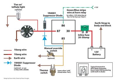
The goal is for the electric cooling fan to run under two circumstances

1 - whenever the thermostatic switch B triggers it because of high coolant temperature. This should trigger the relay at D regardless of the ignition being 'off' or 'on'.

2 - whenever the manual switch A is turned on but only if the ignition is turned on.

Electric-fan-rewire.jpg


Sorry - I was born and raised in the UK and still write 'earth'. US translation = 'ground':usflag:

My main question is: is there any danger if the ignition is 'on' and both the thermostatic switch B and the manual switch A are 'on' simultaneously. I think it should be OK. It means the relay at D will be getting +12v from both sources but I don't think that's a problem and I don't think I need diodes to protect the two switches, do I? Or do I? Any help will be appreciated.

David
 
That will work.
DC- or DC-Com would be more accurate but you have the right idea.
A good sized fuse will be in order for the fan probably 25-30A and stranded copper wire 14gauge or larger.
 
If your manual switch is closed and your temp switch is closed and you turned ignition switch off you would back feed ignition switch circuits until the thermostat switch opened.
 
That will work.
DC- or DC-Com would be more accurate but you have the right idea.
A good sized fuse will be in order for the fan probably 25-30A and stranded copper wire 14gauge or larger.

Thanks. yes, will be using appropriate sized fuses and wiring.

If your manual switch is closed and your temp switch is closed and you turned ignition switch off you would back feed ignition switch circuits until the thermostat switch opened.

Darn. I hadn't though of that. Thanks. Would a diode between switch A and the relay stop that?

David
 
A diode would work since relay coil doesn't draw much current. Also your fan will run after you shut ignition off until the thermostat switch opens.
 
Last edited:
it takes less voltage to ground a circuit than to power it. most new cars fan control's are done that way for longer life of the fan and relays.

Thanks. I see but I'm not sure I can work out how to do it that way and have my initial objectives met - thermostatic switch to operate fan with ignition either off or on but manual switch to only operate fan when ignition is on. Any ideas how to wire that?

David.
 
Just another thought, if the key is off why run the fan? I know it will cool what water is in the radiator but without the engine running to circulate the water it won't cool the engine unless of coarse you have an electric water pump?
 
Just another thought, if the key is off why run the fan? I know it will cool what water is in the radiator but without the engine running to circulate the water it won't cool the engine unless of coarse you have an electric water pump?

Ah! I hadn't realized that. I assumed some degree of convection would continue a low circulation after engine shutdown. My last car was setup from the factory this way to run a fan after shutdown if it was above a certain radiator temperature. Maybe I am trying to be unnecessarily clever?

David
 
Thanks. I see but I'm not sure I can work out how to do it that way and have my initial objectives met - thermostatic switch to operate fan with ignition either off or on but manual switch to only operate fan when ignition is on. Any ideas how to wire that?

David.


gm / chrysler made a ground temp switch use as trigger for on of the fan and the fan can be powered all the time look on you tube for wiring a relay with ground trigger on. using 2 relays can be used for the way you want or with the right relay you could use 1 relay.
 
Thanks for the replies and suggestions ( and circuit diagram ). I will think this through tonight and may be back again with more questions. I really appreciate all the help.

David
 
What you need is a relay with multiple contacts. The normally closed contact will will have 12vdc that has a switch in the circuit. It will send power only when you apply the switch. The normally open contact will have 12vdc from a separate circuit. When the coil is energized the contact closes and sends the 12v through. The coil power will come from the temperature switch. Make sure all power leads are fused. I can draw you a circuit but Im pressed for time right now
 
I already have diagrams and a thread for these ( even being dual fan setup ) to make it work automatically and also manually ( override switch ) ... and with AC compressor sensing too. Will search and post. Even using a lighted override switch which will turn on when fan is working ( either automatically or activating light switch ) lol

I made it being triggered by ground. No need for diodes.
 
Last edited:
What Derwud posted above is what you want, switches trigger on low / ground side, and relay controls power to fan, not the fan ground side.
 
couldn't find the thread but here is a diagram. Is posted for dual fans but works the same with single fan just using what you requires.

If ammeter is being used, relays shouldn't be conected to batt but alt

dual fan option FULL.jpg


here is a set of temp sensors could be used in need of a dual temp setup. These are not Chassis grounded so need to be grounded at the input. It could be used for positive too, but since I made the diagram to be triggered by ground, well...

IMG_1065.jpg
 
The relay for AC here will never be energized? There is no power shown to the coil
The lighted switch option is not shown very clearly?
dual-fan-option-full-jpg.jpg
 
Auto Transport Service
Back
Top