• When you click on links to various merchants on this site and make a purchase, this can result in this site earning a commission. Affiliate programs and affiliations include, but are not limited to, the eBay Partner Network.

100a alternator wiring question.

just a matter of preferences.

Myself, which I love to keep everything of my car working like factory did, would make whatever requiered to keep it on that way just safer, and this includes the ammeter working correctly, of course on a safer enviroment

There is nothing like ear big WOOOWS on car shows when they can tell everything is working order ( every buzzer, light, gauge and accesory ) and not just an unusefull ornament... and this doesn't mean you have to sacrifice anything to add performance

Thats True but the electric system in my car is already chopped,i will buy a aftermarket complete electric system when i have the time to install it.

Ye its really cool if everything that came from factory is working right.

Btw do you have any pics of ur car? :)
 
A voltmeter will tell you whether the alternator is working. If the voltmeter reads above about 12.5-12.8 volts, the alternator/charging system is doing it's job. I find an ammeter to be insignificant. Most of the load is peeled out of the circuit prior to the ammeter anyways in a factory system. It's all in what you want.

Here's an example of a not so smart engineering approach. Some people like to buy the cheap headlight relay kit that is offered on the net. The ad/instructions tells you to connect the main power wire to the starter relay so you can get full battery power.... HUH??? That doesn't work well on a mopar and the battery should not be feeding the headlights when the car is running... that's the alternators job. Now you have the headlight load traveling through the bulkhead charge terminals TWICE and the ammeter instead of once on the way in using the stock system and not through the ammeter at all. Now the ammeter will reflect the load of the headlights when they are on and being fed by the alternator. Genius!

Nachos method works if that is what you are after.

There are a lot of ways to skin a cat. Bottom line to all of them is get the charge load off the substandard bulkhead connectors and factory wiring.
 
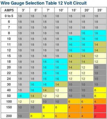
This may help
12VDC_wire_gauge_chart.jpg
 
While I like and prefer to keep the ammeter function as it was originally intended in the car, and understand what it is telling me, most guys don't understand that it shows battery charge/discharge and could care less. Additionally, interpreting charging system condition from a voltmeter is easier for most people.

So, with all of that, the bypass from alt output to starter stud is an easy thing to install, gets at least the battery charging load off of the bulkhead connections, and splits the remaining loads between 2 bulkhead connectors (which is like what Nacho does in another way, in reality). The loss of the proper ammeter function and use of a voltmeter instead works well for most people, so for an upgrade that is fairly effective, the bypass method works OK.


Still im wondering if I need to add a wire from starter relay stud to the battery ofc same size as the one from alt to starter stud?
 
I personally would not, unless that present wire from battery to starter relays' big stud is much smaller....which it should not be in stock form. My reasoning is that the regulation of the charging system is a form of feedback-control system, with some internal time delays that can become a bit unstable without some level of resistive damping.....i.e., the voltage regulation can 'hunt' up and down continuously without some level of resistance in the system. This has been reported in couple of cases where the alternator output is connected directly to the battery +. But, you can always try it, and if the voltage is stable then that is OK.
 
I personally would not, unless that present wire from battery to starter relays' big stud is much smaller....which it should not be in stock form. My reasoning is that the regulation of the charging system is a form of feedback-control system, with some internal time delays that can become a bit unstable without some level of resistive damping.....i.e., the voltage regulation can 'hunt' up and down continuously without some level of resistance in the system. This has been reported in couple of cases where the alternator output is connected directly to the battery +. But, you can always try it, and if the voltage is stable then that is OK.

My alternator has built in regulator since its a bosch alternator.

But my wire from starter stud is going to the starter is it supposed to do that?

So from alt to starter stud from starter stud to battery?
Or from alt directly to battery?
 
The suggestion is for the alternator output to go to the big lug on the starter relay. That 'big lug' should not have a wire going to the starter. Stock, it should have one wire from the battery and another wire (the fusible link) going to the firewall.

The wire from the starter relay to the starter should connected to the different terminal on the starter relay. Look at the picture of a starter relay on the thread titled "Troubleshooting neutral safety switch ". The smaller starter wire goes to the S terminal, and the small battery wire, fusible link to the firewall, and now the alternator output will connect to the B terminal (the 'big lug').

If you do not have a diagram of your car, go to www.mymopar.com and find your car's schematic.

Weird my cable from battery goes to the starter,thanks alot for everything i will try to figure it out but im not really good at electrical stuff.
 
The main cable goes to the starter. There should be a secondary cable, about 10 gauge that runs from the battery cable end to your starter relay.
 
The main cable goes to the starter. There should be a secondary cable, about 10 gauge that runs from the battery cable end to your starter relay.

Is the secondary cable supposed to connect at the big stud on the starter relay?
 
A voltmeter will tell you whether the alternator is working. If the voltmeter reads above about 12.5-12.8 volts, the alternator/charging system is doing it's job. I find an ammeter to be insignificant. Most of the load is peeled out of the circuit prior to the ammeter anyways in a factory system. It's all in what you want.

Here's an example of a not so smart engineering approach. Some people like to buy the cheap headlight relay kit that is offered on the net. The ad/instructions tells you to connect the main power wire to the starter relay so you can get full battery power.... HUH??? That doesn't work well on a mopar and the battery should not be feeding the headlights when the car is running... that's the alternators job. Now you have the headlight load traveling through the bulkhead charge terminals TWICE and the ammeter instead of once on the way in using the stock system and not through the ammeter at all. Now the ammeter will reflect the load of the headlights when they are on and being fed by the alternator. Genius!

Nachos method works if that is what you are after.

There are a lot of ways to skin a cat. Bottom line to all of them is get the charge load off the substandard bulkhead connectors and factory wiring.

perfectly told

- - - Updated - - -

While I like and prefer to keep the ammeter function as it was originally intended in the car, and understand what it is telling me, most guys don't understand that it shows battery charge/discharge and could care less. Additionally, interpreting charging system condition from a voltmeter is easier for most people.

So, with all of that, the bypass from alt output to starter stud is an easy thing to install, gets at least the battery charging load off of the bulkhead connections, and splits the remaining loads between 2 bulkhead connectors (which is like what Nacho does in another way, in reality). The loss of the proper ammeter function and use of a voltmeter instead works well for most people, so for an upgrade that is fairly effective, the bypass method works OK.

yeap

- - - Updated - - -

The main cable goes to the starter. There should be a secondary cable, about 10 gauge that runs from the battery cable end to your starter relay.


this has being changed allong the years and bodies. MOSTLY of cars got it with secondary cable between starter motor battery cable end, and some other got from battery cable BATTERY end. 73/74s B bodies got it on the last one ( mine is 74 and is on that way ): can't recall how was set every one

- - - Updated - - -

Btw do you have any pics of ur car? :)

since you asked:

575702_10151418686113753_814421669_n.jpg
 
Sweet car nacho, I have read quite a few of your posts and plan on doing the parallel wiring to take the load off the bulkhead connector at the very least. My car (70 gtx) is 100% stock wiring now and I have owned it for over 35 years, although all the wiring and connectors look good and I never had a problem I just want the added insurance.
Everything in my car also works exactly as it should, gauges, lights mechanical you name it it works perfectly and I want to keep it that way.

I do have a question for you, I was considering upgrading my headlamps to halogen without using relays or anything, would the draw be too much?

Keep giving us your your advice, I appreciate it.
 
Last edited:
While I like and prefer to keep the ammeter function as it was originally intended in the car, and understand what it is telling me, most guys don't understand that it shows battery charge/discharge and could care less. Additionally, interpreting charging system condition from a voltmeter is easier for most people...
I agree. The only problem with a voltmeter is that it doesn't show if the alternator is charging the battery, a reading over 12.8 Volts is a good indication of charging, but only a guess...nothing more. An ammeter shows the actual charge/discharge.
 
One thing to note: seeing 12.8 or so from the alternator is NOT an adequate test of the alternator. You can see even over 13 volts from the alternator with all but one diode blown, and you can see the high 12 volt range with the regulator blown and just the residual magnetism in the rotor core mildly exciting the alternator.

The one and only truly valid one voltage test is like the factory wrote it up: look for 13.7-14.3 volts across the battery when at FAST idle and warmed up (and the system connections being good). Being at cruise RPMs' should show close to the the same voltage. Reading the voltage in this way is a valid test and is a good reference for things going wrong in the system. You can sometimes see that a diode is blown if you get consistently lower voltages running at a given RPM and with a known loading condition. And you will get slightly higher system voltages when it is cold and lower when really hot outside.

The problem with reading an ammeter is that sometimes the same indication can mean different things. For example, a slight discharge may indicate that the charging system has failed and you have a light load on the system. But a slight discharge can also occur after you have driven for a long time at cruise RPM's and charged the battery up good, and then you turn on a load like the headlights. This occurs especially with a low output alternator (like the 35A one) because the added load will lower the alternator output voltage and the well charged battery will discharge slightly for a short time to 'equalize' to that lower system voltage. So ammeters can be ambiguous.

These car batteries will be charging at anything above about 13 volts, but not much at that voltage. They can't 'self-generate' a higher voltage, except via surface charge effects, which is something that results from charging. So the above test of looking for 13.7-14.3 volts with the system warmed up and at RPM's in the fast idle or cruise range, will indeed indicate a charge. (Well, unless the battery has opened up internally!)

- - - Updated - - -

I do have a question for you, I was considering upgrading my headlamps to halogen without using relays or anything, would the draw be too much?
If you don't mind my chiming in, the standard, off-the-shelf, sealed beam halogens draw the same current as the non-halogen incandescents. I am not sure where the idea came from that they draw more, unless they are being confused with the aftermarket quartz iodide or other halogen bulb types with the separate bulbs and lens/reflector assemblies.
 
If you don't mind my chiming in, the standard, off-the-shelf, sealed beam halogens draw the same current as the non-halogen incandescents. I am not sure where the idea came from that they draw more, unless they are being confused with the aftermarket quartz iodide or other halogen bulb types with the separate bulbs and lens/reflector assemblies.

Thanks, yea I was under the impression that they where higher wattage and draw more current,( and I am talking about the sealed beam type ).
That's great to know, I'll grab a set at the parts store and swap them out and hopefully see a bit better driving at night.
 
Increased lamp load is only one consideration for installing headlamp relays. Removing the voltage drop across the stock 40+ year old small wiring, switches & connections will bring marked improvement in performance even with factory type sealed beams.
 
Increased lamp load is only one consideration for installing headlamp relays. Removing the voltage drop across the stock 40+ year old small wiring, switches & connections will bring marked improvement in performance even with factory type sealed beams.

That is spot on. The changes people report when using the kit I build are substantial, even with the old sealed bulb. Halogens are a step up.

Larger wire sizing creates less voltage drop along the runs. Multiple connection in a run creates resistance, thus voltage drop. Headlight performance degrades exponentially with voltage loss. A 10% loss of voltage may create a 15-20% loss in light output.
 
Very valid points guys.
 
Auto Transport Service
Back
Top