• When you click on links to various merchants on this site and make a purchase, this can result in this site earning a commission. Affiliate programs and affiliations include, but are not limited to, the eBay Partner Network.

383 Waterpump holes - What goes where??

Normal temp gauge on my 69 Bee Rallye dash, no idiot light. However, I prefer to have a more accurate aftermarket gauge, but also like operating dash gauges since they're there. Same with aftermarket oil pressure gauge.

440beep - so from your last pic you are showing fittings in both w/p holes - Small one goes to idiot light? Big one with AN fittings to aftermarket temp gauge? Do you NOT have factory temp gauge?

short stack
 
Mine are AFTERMARKET - Aluminum CFV I think. Not my choice for sure, but something that the guy Im putting the car together for really wants.

So, I want to run inside pulley to alternator and outside to p/steering. Will this make alt and p/s run in the correct direction?

short stack

they will always run in the "correct" direction. Looks as if the crank pulley us an under-driven style. Looks like the groves are the same size on each pulley, but the spacing for the groves is farther apart than stock, which means you are gonna have to do some spacing of the PS pump and maybe the alternator for belts to run true on each groove.

Also, note that the crank pulley is smaller than stock, which means the alternator & water pump are going to spin slower than normal as well. Which means lower alt output at idle and slower water movement in engine at idle as well.

Seems an awful lotta work to me....I would get with customer and see if this is really what he wants.

One more thing, you will need to run belts of the same "width" to avoid belt squeal also
 
Since were talking about cars, the small hole on the right (driver's) side is 1/8" IPT (tapered pipe threads). The hole on the left is 3/8" IPT. IPT stands for International Pipe Threads. End of lesson.
 
Don't you mean NPT, national pipe threads? Never heard of international....has something changed?
 
NPT for US. IPT for world. Both standards for 'tapered pipe thread'.
 
Cool, I learned something! Thanks Dave!!
 
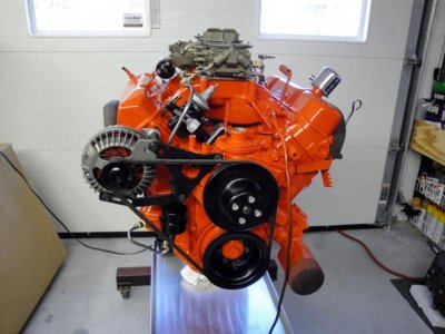
Here's an awesome picture of somebody's motor (I think a member here?). Great shot of the vapor separator. I've referenced this picture frequently during my build.

alternator.jpg
 
Can one of you gentleman tell me which “port” is the inlet and which “port” is the outlet for the heater hoses?

Thanks, John
 
Six Pack6.jpg

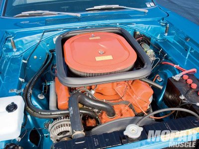
Here's a picture of a Six Pack 440 Bee with the heater hose layout. 1969 Service Manual confirms this layout for 383 and 440 engines. Note how the hoses crossover each other.

Front waterpump port goes to driver side outlet port on firewall. Rear waterpump port goes to passenger side inlet port.
 
Thanks to everyone posting on this thread, some good info getting brought up and I was always curious why I had 2 temp senders as well.

As long as this is kindof turning into an "engine accessory correctness" thread, does anyone have any pics/explanation on how the fuel lines are routed from the main lines to the fuel pump and up to the carb on a 440 w/stock carter avs and fuel pump setup?

I have my main sending and return lines in place and pump-to-carb lines ready to hook up, just not sure which lines go where on the pump, do I need a special vapor separator or would just a generic cannister filter work, etc?
 
Auto Transport Service
Back
Top