• When you click on links to various merchants on this site and make a purchase, this can result in this site earning a commission. Affiliate programs and affiliations include, but are not limited to, the eBay Partner Network.

Cam button use

One thing I will not do..........is tell you to do something that I have not put my own *** on the line trying first.

I believe that. When IQ52 advises something, that's the last word IMO. And, after seeing how a cam wants to walk right out of the engine at 120rpm, I have zero confidence that even with a timing chain installed and valve spring pressure pushing down on everything a cam would not be able to move enough to bite the cover at 6000rpm.
I'll use a button.
(When I can convince my hands to pry open my wallet enough to go
to a proper roller setup, that is:D!)
 
So...am I to understand that a cam button is ONLY necessary on a roller cam setup? Otherwise the gear drive should keep the cam in it's place on a SFT cam like mine?
 
Reread the whole thread, most importantly about the tapered lobes holding the cam in.:thumbsup:

Thanks to IQ52 for the good information.
So...am I to understand that a cam button is ONLY necessary on a roller cam setup? Otherwise the gear drive should keep the cam in it's place on a SFT cam like mine?
 
So...am I to understand that a cam button is ONLY necessary on a roller cam setup? Otherwise the gear drive should keep the cam in it's place on a SFT cam like mine?
Yes and no...it's the lobe taper of the FT, not the gears that thrust the cam rearward.
Roller cam lobes have no taper, because the lifters don't rotate during operation like flat-tappets have to.
 
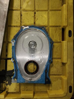
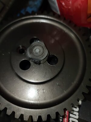
Well here it is in all its glory...I also checked the the fitment of the button into the sprocket and it is pretty loose. Don't know but it looks like the cover wore down the face of the button as there is "flashing hanging off the edge..which may have allowed it to fall out after a while of reving and idling.

20210623_151443.jpg 20210623_151649.jpg
 
Last edited:
Bear in mind the camshaft gear is the driven side, in a case like this the oil pump gear just follows the cam and does not provide any rotational force to push the cam into the engine block.
Note: As a matter of fact, the opposite force created by the oil pump (pressure build up) is creating an opposite force at the gear, so basically the higher the oil pressure the more strong this force becomes and is something where the camshaft is pushing against...and in the way the gears are cut pushing the cam out of the engine.
On the other hand, the camshaft rotation is placing a axial force on the pump drive gear and pushing it down against it's thrust bearing/bushing...if the gearing was cut the other way the oil pump drive shaft would be lifted out of place.

Installing a roller cam it becomes a "floating" setup, as the rollers also do not provide any inward force like the flat tappet lifters do.
The engine was designed with a thrust surface for the cam to run against with "inward" force provided by the lifters and their angled lobe design, yet the roller lifter does not provide this ability and requires to be retained in another manner which is a cam button's job.

Going to a roller cam, you remove the only feature (from the ft cam) that retained the cam with "inward" force which must be replaced with an alternative option.
 
Last edited:
So Mike67, you have a straight cut gear drive on the engine? I can actually see the marks that your idler gear
left on the cover! Do you have a pic of the cam and intermediate shaft from inside the valley? Also, a pic of
the block thrust face? Thanks!
 
So Mike67, you have a straight cut gear drive on the engine? I can actually see the marks that your idler gear
left on the cover! Do you have a pic of the cam and intermediate shaft from inside the valley? Also, a pic of
the block thrust face? Thanks!

There are a couple pics of the cam lobes in my thread, but no I didn't take any of the intermediate or cam gear. I had to run to the shop real quick and figured I could snap these real quick.
I looked at the i-shaft and there was no sign of damage to the bronze gear that I could see.
Well does this change your mind about needing a button???
 
Well here it is in all its glory...I also checked the the fitment of the button into the sprocket and it is pretty loose. Don't know but it looks like the cover wore down the face of the button as there is "flashing hanging off the edge..which may have allowed it to fall out after a while of reving and idling.

View attachment 1128537 View attachment 1128538
Was there not enough clearance or was there too much clearance? Kim
 
Was there not enough clearance or was there too much clearance? Kim

I dropped my oil pan before removing the engine, it appeared that the water pump may have pushed back on the cover, it was definitely in contact with it and what I presumed was the cause. I never thought to check and see if it deflected cover enough to close the clearance during assembly, (novice). Secondly there were no warnings that came with the Source Cover, they are actually on their website...lol! And like most parts ,it was purchased a couple of years ago, so I didn't even think about to be honest. All I wanted was the right clearance to the cover and from the block to the back of the axle...
Here is an excerpt from Sources aluminium cover ad..."On our test engines, we've found our passenger side aluminum water pump housings work great with no interference at all while our drivers side housings require slight grinding on the back at the area of the bulge where the lower hose attaches. After some slight grinding, they fit great also with no problem. Also, please note: some modification of cam buttons and/or cam attaching bolt heads may be required due to the slightly reduced space between the front of the cam and the back of the cover. This is because of the increased thickness of the front of the cover. If we would have restored this cam to inside cover dimension back to factory, this cover would not have been able to work with cast iron or aluminum type water pump housings."
I feel pretty dumb about the whole thing to tell you the truth...
 
If you read my post i said it was the Head of Operations, and I asked if I could publish his name.
He said he did Not want me to do that because he knew what a **** storm this was going to cause.
I'm going to try and get someone who won't mind me plastering their name on the forum and maybe
we can get somewhere? Until then, I'm listening to everyone's comments and finding out what everyone
is doing for their specific setup.

A prominent figure in the performance industry and he's afraid to put his experience out there. Double funny.
 
A prominent figure in the performance industry and he's afraid to put his experience out there. Double funny.

You know how it goes here on these forums, he is either right or wrong but with so many people having an opinion he is going to get crusified regardless what he is going to say.
 
An interesting read.
I've seen engines run backwards when shut down due to carbon build up and dieseling!
Would this push the camshafts in the opposite direction! And cause some damage? Just asking?
 
Would this push the camshafts in the opposite direction!

No, because the flat tappet lifters are still pushing the cam inwards regardless of direction.
Your oil pump drive shaft does see an upwards force and will push against the distributor but that will not be enough force to damage something there.

You sure you have seen an engine run backwards due to dieseling? Mostly they will continue in normal rotational direction.

Yes. Although not long.
 
Camshaft Thrust Buttons are a must do for Roller Cam applications, because of the Higher V/Spring Pressures and the Roller Lifter Wheels/Trunions can create sufficient thrust on the Cam Forward in the Block during operation to overcome the normal rearward thrust created by the Cam Helical Cut Gear in mesh and driving the intermediate/Oil Pump shaft..... then pushing the Cam out the front of the engine.

Flat Tappet Cams do not require a Thrust Button,
because although the Lifters create minimal end to end Thrust it is rearward anyways, and the normal engagement act of the Helical Cut Gear on the Cam driving the Intermediate Oil Pump Shaft creates more than sufficient rearward thrust to maintain the Cam in the Block.
 
So Mr. Ray Barton was gracious enough to return my phone call this morning. It seems that
a roller cam does indeed need a cam button to keep it in place! Wow, that hurts! I've collected
all of my brain cells, and they are in re-training mode. Sorry I got everyone in an uproar, and
now I know if I ever put a roller in my engine it'll be the right way. I stand Humbly corrected!
 
Auto Transport Service
Back
Top