• When you click on links to various merchants on this site and make a purchase, this can result in this site earning a commission. Affiliate programs and affiliations include, but are not limited to, the eBay Partner Network.

Charging/ammeter issue

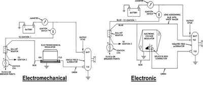
Generally, electronic regulators are more accurate/reliable than their mechanical counterparts. There are direct replacement electronic versions on the market for the pre-’70 applications. The square-back alternators were designed for the 1970 and later factory electronic regulation, have two field connections “isolated” from the alternator case. They can be modified for use with pre-70 regulators and there is significant benefit to running the later higher output alternators, more charge current available at idle.

There are plenty of threads here that address what can go wrong when you mismatch these alternators & regulators.

To be clear, the no start condition described here has nothing to with the charging system.
 
Last edited:
Generally, electronic regulators are more accurate/reliable than their mechanical counterparts. There are direct replacement electronic versions on the market for the pre-’70 applications. The square-back alternators were designed for the 1970 and later factory electronic regulation, have two field connections “isolated” from the alternator case. They can be modified for use with pre-70 regulators. There are plenty of threads here that address what can go wrong when you mismatch these alternators & regulators.

To be clear, the no start condition described here has nothing to with the charging system.
Thanks very much. I just learned something about the Alt I’m using. Appreciate the help!
 
My advice would be to convert to running the ’70 and later electronic regulator, keep the square-back for the higher idle output. Requires adding another wire run from the VR to the alternator and the VR pig-tail connector for ’70 and later. Otherwise, a simple conversion. Would also verify the "parts-store” square-back is assembled correctly as relating to field terminal insulators.
 
Usually a fully charged "good" battery at rest is somewhere between 12.75 and 13.0 Volts.
They do vary depending on how recently it was charged and if you have small currrent draw in the vehicle at rest.
 
My advice would be to convert to running the ’70 and later electronic regulator, keep the square-back for the higher idle output. Requires adding another wire run from the VR to the alternator and the VR pig-tail connector for ’70 and later. Otherwise, a simple conversion. Would also verify the "parts-store” square-back is assembled correctly as relating to field terminal insulators.
Is this the wiring change you're talking about (found from vsandhurst here). is the pigtail available?

alt dia.jpg
 
The 69 and earlier are non isolated field, it basically pulses current through the rotor windings to make a magnetic field that spins through the stationary windings to generate alternating current (alternator name). The diodes in the round back, and solid state rectifier in the square back just, to use a visual kind of reference, filter off the positive side of the sine wave and with the different sections in the stationary windings, they overlap/smoothing the pulsing.
The voltage regulator should have no relation to pulsing. However, a old mechanical one with the solenoid operated contacts could at low rpm cause voltage "pulsing" as it loads the field and the alternator is struggling to keep up at such a low rpm, add in a low battery and pulsing is possible.
I have a square back with a 69 and earlier electronic conversion regulator, it does pulse very little, but it may be my alternator (it's old) and not enough to bother me.
 
Actually one of the fields is isolated. On laters are both.
70 up are isolated field. They technically ground through the regulator case. The electronics inside the 70 up control the grounding at a more infinite level that the contact points on/off switching. If no power in the 70 up regulator it has no connection to ground, hence the term isolated field.
 
70 up are isolated field. They technically ground through the regulator case. The electronics inside the 70 up control the grounding at a more infinite level that the contact points on/off switching. If no power in the 70 up regulator it has no connection to ground, hence the term isolated field.

Well said.....re your # 29 post, actually the diode assemblies in either the round back (individual diodes) or square back (modular diodes) design are connected in a three phase full wave bridge rectifier circuit, with the Stator windings connected in a WYE configuration. An alternator of this configuration yields a very low ripple waveform due to the bridge configuration. The only real influence factor is the operating RPM. A 3 phase full wave bridge rectifier circuit will typically present a 400 Hz waveform at a nominal cruise engine speed, b4 rectification. But frequency is determined by the number of North & South poles of the rotating field and the field's operating speed. Post # 28 & # 30 has been presented repeatedly, ~ 200+ times.....just like a broken record.....perhaps he should listen and learn.....just a thought....
BOB RENTON
 
Once again... one of he brushes/fields remains isolated on the earlier system. On laters are both. Dunno what's wrong with that statement. Even diagrams shows the word FIELDS at the brushes... and the alt case is casted the letters FLD.


70alt-jpg.jpg


226778-300b52efdc799326e6169394f82969fd-jpg.jpg


Still on the "single field" alt...

alt_rear_bearing_dimpled-jpg-jpg.jpg


Definitelly you are obssesed with any of my replies searching for anything to critic.

I didn't offer any other detail about how it works one or the other ( which I can talk also without too much technicality for average ppl trying to help ).
 
Last edited:
70 up are isolated field. They technically ground through the regulator case. The electronics inside the 70 up control the grounding at a more infinite level that the contact points on/off switching. If no power in the 70 up regulator it has no connection to ground, hence the term isolated field.

sure! the elect reg uses the Ign1 source to be able to operate, just like the mech reg also needs the chassis ground to operate. On the elect regulators, one is wired due the nature of the new design, the mechs not because is constantly closed to ground not for regulation but for operation ( althought on both cases regulation is involved of course ). Is just like a bulb... needs both sides to operate. You cut any of both sides and won't light up.

Personally I never have read the isolation system being called by the regulator nature ( which is also ) but by the brushes setup which is pretty much the obvious
 
Last edited:
sure! the elect reg uses the Ign1 source to be able to operate, just like the mech reg also needs the chassis ground to operate. On the elect regulators, one is wired due the nature of the new design, the mechs not because is constantly closed to ground not for regulation but for operation ( althought on both cases regulation is involved of course
The 69 and earlier only needs the ground to operate the coil inside the regulator. The ground on the regulator is in no way connected to the field wire. Ground for the field is provided by grounded field terminal on the actual alternator.
70 up that wire leads back to voltage regulator where it is electronically switched to ground. The field is isolated by a switch on each side, positive by ignition switch, negative by a transistor in the voltage regulator.
Using your light bulb analogy, both the positive and the negative are switched from the power, and ground sources, hence isolated.
Hope this helps.
 
I have to say that I am completely blown away by the knowledge you people possess. Your answers to my question has caused me to study and better understand my charging system, something we rarely think about ‘til it stops working. I now understand it a little better but not to the degree laid out in your answers. My background is in film production and I can tell you how color temperatures in lighting affect how you see the color of your car, but you guys are just really bright, and damn smart. Thanks for all the help.
 
The 69 and earlier only needs the ground to operate the coil inside the regulator. The ground on the regulator is in no way connected to the field wire. Ground for the field is provided by grounded field terminal on the actual alternator.
70 up that wire leads back to voltage regulator where it is electronically switched to ground. The field is isolated by a switch on each side, positive by ignition switch, negative by a transistor in the voltage regulator.
Using your light bulb analogy, both the positive and the negative are switched from the power, and ground sources, hence isolated.
Hope this helps.
Sure I know that, just that I'm looking at from a diff perspective.
 
Auto Transport Service
Back
Top