• When you click on links to various merchants on this site and make a purchase, this can result in this site earning a commission. Affiliate programs and affiliations include, but are not limited to, the eBay Partner Network.

Degree an installed/unknown camshaft

I read all those articles indeed.
I did not figure it out because i am so smart, i was just smart enough to follow your advice to read up and learn.:rofl:

Also those other links posted and other treads i found online (FBBO FABO) about reactions people got from tech support or info on the websites of major cam grinders is shocking to say the least.
After reading up and you got i figured out you do not expect these answers and advises to come from the big cam company’s! :eek:

But just wondering, what height increase are we talking?
Can i at least try first with a shim kit (0.020” and 0.040”) to raise it or are we generally talking much more?
Because instead of dropping, say, 0.100” of shims in there it think it would be better to get some more solid stuff like B3 is selling.
Adding 0.040-0.060” shims would be not a big thing i believe, right?
The problem with regular shims is two-fold: they can cause increased pressure on the radius of the pedestals, which some have reported causes cracks(I've never seen it happen personally). The other and more obvious problem is, they move the shaft up, and closer to the valves...we need to be moving up and away from the valves most of the time. So the hughes/440 source/mancini shims make geometry worse 90% of the time..
 
Yeah, very true.
And i think that is where the kit from B3 comes in, because that will not only lift the rocker shaft but also allows it to be moved away/towards the valves as required.

If you look at the angle of the rocker shaft supports it will always move towards the valves.
That's why i was thinking if it is worth to shim it which improves things.
But as you said it will move closer to the valves, which is something you don't want but this actually only changes the location of the contact. (center/rocker shaft side/exhaust side.
If the benefits are greater than the negatives, it will narrow the contact pattern to acceptable size.

But i don't want to end up with a spacer made of shims, that's why i wonder what is the "average" if there is such thing, that one should shim when changing from stock rockers to a roller rocker?
1 or 2 shims is not bad i guess, but a stack of the bastards does not seem the right way, and in that case the kit from B3 is a good alternative to get it set up.
Just for exploratory purposes, cut the side out of an aluminum can, and cut some little strips. Fold them over until they are .030 thick and slide one under he shaft, on each side of the hold-down bolts. You'll get a rough idea of the effect....I have the harland sharp/mancini rockers on Edelbrock RPM heads with (only)a .526 lift cam and my B3 spacers are moving the shaft approximately .250"...the swipe was centered before, but wide at over .130"! It's still centered and more like .030 or just under that.
 
So, best bet would be to go for a B3 kit straight away then i guess.
When i will get close of going home i will contact him and see what he will require from me to gather a package that will work on my engine.
Someone said he will send some file to complete with measurements or so?
 
Yes, he'll email you a form with more questions and instructions on getting some measurements.
Now, some things you should know in case you don't already-
Elongating the hold down holes in your rocker shafts will be required, which means also removing & reinstalling the end plugs and getting them cleaned spotless. I did mine with a dremel and carbide burrs; and while it's not difficult, it was messy and time consuming...those shafts are tough. Mike will do it for you for an extra fee, next time I will go this route and let him do it in his shop.
-If you elect to use his spacers you need to get them on your heads before you measure and order your pushrods.
 
good advice beanhead
thanks for posting
back in the day we cut the stands off and made new stand blocks like the early heads had- lot more work than B3
 
Ok, thx for that additional info. I was not yet aware of that.
By elongating you mean the holes require to be made oval shape, or just bigger in diameter?
Guess B3 their spacers might center in that hole when installing?

I got a Dremel as well and a straight large pencil grinder but that thing has any steel for breakfast so i think that is a little overkill, see what is required though.
Sending it in is a bit pricey for me from Europe so i will have to do this myself, no problem.
Guess the end plugs he can include in the package for me.

So you receive his kit, is this a straight setup with his spacers?
Just install it as they come and check geometry, measure up what length push rods i need and get them.
I also need to get an adjustable push rod to check the length required.

Edit: What range pushrod length checker would be ok to use? Going from stock-ish length and up. (stock is 8.575" right?)
Found one from Proform, 8.500 - 9.800" which i believe is enough right?

back in the day we cut the stands off and made new stand blocks like the early heads had- lot more work than B3

More work but then if everything is right the geometry works out perfect.
 
Last edited:
Ok, thx for that additional info. I was not yet aware of that.
By elongating you mean the holes require to be made oval shape, or just bigger in diameter?
Guess B3 their spacers might center in that hole when installing?

--Yes, elongating. Due to the way the shaft must move, the hold-down bolts' position through the shaft changes a little. The bolt head/hold down block will not sit properly without this mod.


Guess the end plugs he can include in the package for me.

--I reused mine. Swiped a very small amount of gray silicone around the mating edge. (Remove them carefully! They just tap out from the inside)


Edit: What range pushrod length checker would be ok to use? Going from stock-ish length and up. (stock is 8.575" right?)
Found one from Proform, 8.500 - 9.800" which i believe is enough right?

--that size is good for R/B engine.

(Expand the quote box to see reply)
 
"More work but then if everything is right the geometry works out perfect."
Thanks
but that assumes we knew what we were doing back then
still learning
 
back then

Indeed, and nowdays the knowledge is gone.
All engineering is chewed for you by the car manufacturer, you only have to swallow.
Drive into any "modern" garage with some "modern" mechanics and they be looking all over your Mopar for the OBD plug.
That is why it is so nice that forums like this exists where these things are being passed on for other generations to keep these classic icons on the road!

So i will get some tools and materials when i get home and soon send a mail to B3 to see what we can do.
Anyone any idea what it costs for making a kit like that?
 
Mine was just under $200 U.S , shipped. Seeing as you're overseas though I expect it will be more..
 
Yes, i already got used to the extra charges of shipping and import taxes....:BangHead:
 
Unfortunatly i will have to stay at work a little longer.. :(
I already ordered some stuff to do the work, checking springs, valve compressor, push rod length checker.
Also ordered some billet steel hold downs from Hughes and shims to do some adjustment if required.
These current hold downs look quite flimsy, when i see their billet ones made me believe i need them.
Also ordered the shims for below the rocker shaft to raise it, just want to try and see what it brings.
Likely it will end up mismatched, even though it would just be for the experience to play with it.

I have read the below instructions and want to try and see what i get.
http://www.hughesengines.com/Upload/productInstructions/HUG8220.pdf

Just made me wonder where to start, i still need to check the piston to valve clearance, but from my understanding the valve lift might change slightly after getting the correction done on the rocker shaft so no real point to do that first i guess. (unless i can just substract the future lift difference from the PV clearance i measure with this setup its lift)
Determine the push rod length will be the last thing i believe.

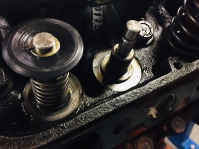
I will install the checking spring on #1 cylinder, then i can also check if the retainers are ok or not and get the spring tension measured up just to see if they are sufficient.
 
Hey guys,

Back home again, after the first few days home just caring about the primary's in life, "drink, eat, sleep, repeat" i started to work on the car again.
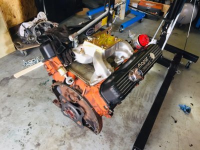
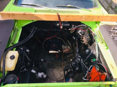
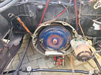
Just completed pulling the engine out and mounted on the engine stand, had to make some longer support brackets to reach the bottom bolt holes but anyway, she is snug.
Still have to tidy up and cover up the car as it will have to stay outside, later i will get onto the valve train and install the checking springs on cylinder #1.
After the weekend i will bring the original springs to my engine builder to check for the spring tension and see what that brings.
He also told me the springs will all act a little different but i guess it will be showing the springs are stock or have a higher tension. (comparable with the Hughes 1106 springs)

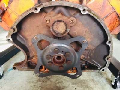
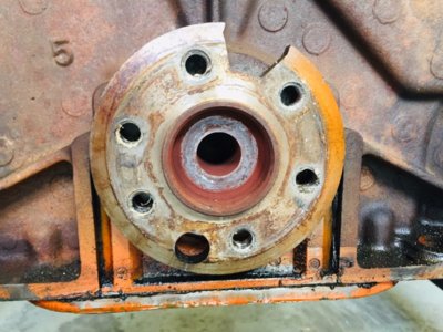
Some pictures of the crime scene, i did notice this cut out in the flex plate hub.
Is that normal??

IMG_3733.jpg IMG_3734.jpg IMG_3735.jpg IMG_3736.jpg IMG_3737.jpg
 
So, i had the checking spring installed and checked piston to valve clearance.
I found the tightest spots as per below:

Exhaust: 0.099" @ 10* BTDC
Intake: 0.136" @ 5* ATDC

This is with the current setup, i assume that after changing the geometry i will see an increase in valve lift which will reduce these clearances.
Just hope it is not too much.
I will have to fabricate a stand for my dial gauge to set it up to measure the valve lift at the spring retainer to get an accurate reading so i have something to compare afterwards.
Also found that when looking through the spark plug hole the pistons have valve recesses, so no flat tops. The number L2355 is stamped in the top.
 
Last edited:
Thx, i was afraid already someone cut a piece out for reason unknown and now is a problem :D
Good to know it is as it is supposed to be :thumbsup:
 
I had checked the valve lift at the valve retainer by using the checking springs, had the rest of the rockers removed so just cylinder #1 valve train moving.

Exhaust: 0.587" As per cam specs 0.576")
Intake: 0.580" (As per cam specs 0.572")

I think with the current geometry being as good as it gets without going into repositioning the rocker shaft as the actual valve lift is more as advertised.
The rocker roller contact patern on the valve stem is about 0.077" wide, which is a goal to reduce this.
Still want to check where the valve is at half lift, below/above the rocker shaft centerline.
I might get away with a shim or 2 below the rocker shaft to get the contact patern more tight.

Regarding the valve retainers, i measured them and found they have a shoulder of 1.025", the spring ID (without damper) is 1.130" which gives quite some slack to be honest.
The centering shoulder machined on the head is 0.992", but given the ID of the damper is 1.008" so i guess centers there without issues.
I send a mail to Hughes to advice what retainers to use, the next retainer which will give a more tight clearance for the outer spring is the HUG 1254, which has a shoulder of 1.060", but this adds 0.075" more height space which i don't want because the installed height is 1.912" already. (Hughes advices 1.880" for the HUG 1106 springs which i think these are as well)
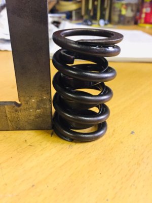
And i need new springs i think, i found that when held against a straight edge the are not straight anymore.
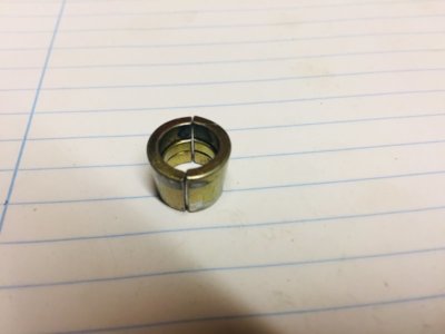
Will get some new keepers as well, but this time i think i will go for the machined ones as these seem to be the stamped version.

IMG_3738.jpg IMG_3740.jpg IMG_3742.jpg
 
My engine builder helped me out and checked the spring tension for me.

Installed height: 138lb @ 1.912"
Full lift: 328lb @ 0.586" lift

This is obviously just an average of all of them, also bear in mind they are used.
 
I already also noticed that there is a difference in the valve spring installed height, when i install new springs i will have to shim them to make them all similar height.
What is the tolerance there, as close as possible?
Like now i measured 0.032" difference between intake and exhaust valve on cylinder #1.
I found some shims on Summit which will fit my heads, OD 1,500" and ID 1.031".
Spring OD is 1.540" and the shoulder on the head is 0.992", it is not a tight fit, is that a problem?
These shims come in 0.015", 0.030" and 0.060" thickness which will eliminate most of the difference i guess but it will not be "0" difference.
 
Auto Transport Service
Back
Top