• When you click on links to various merchants on this site and make a purchase, this can result in this site earning a commission. Affiliate programs and affiliations include, but are not limited to, the eBay Partner Network.

Degree an installed/unknown camshaft

Not using a Landis CNC grinder here
old school
on some you have a Vernier divider to set the angle of the lobe
and have to set every lobe by hand (I am lousey at this)(on the very few I have
done)
others you set the first one then there are notches every 45 degrees so (for a V8) you can more quickly grind all the Intakes
then you do the same drill with the exhausts
keep the wheel dressed
maybe change to a newer/ finer stone and "spark out" the final pass
Those Engle grinds were first introduced in the late 1990's or early 2000's
you know what computers were like back then
(slightly later than Comp 168 UD Harold period- about Ultradyne time frame)
they may have been re-mastered
Incidentally Jack Engle was a good friend of Dick Jones- father of Mike and Rick

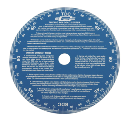
Weitse are you using a 180 degree or 90 degree degree wheel?
 
The degree wheel is divided in sections of 90*

Schermafbeelding 2019-08-23 om 00.46.47.png
 
The Ica is the Intake closing Angle and is the thing you are measuring.
You cannot measure the Lobe centerline; you have to infer it.
For your cam,Hughes lists the intake opening point as 14* and then you rotate the engine until the valve begins to close and you find that point is 44 ABDC. Between TDC and BDC is 180* the distance you rotated.
Ok so add that all together;
14+180+44=238* the intake duration measured at .050 tappet rise.
So now to find the centerline you do math to infer it. The halfway point of 238 degrees is119 the centerline of the lobe. But where is it relative to TDC? Well if you did it right, Hughes says 14* of those degrees are on the otherside of TDC, the Before side,so subtract 14 from the 119 and you have the inferred centerline of 105* After TDC. Since if the cam was installed at straight up, the centerline would be at 108*, this 105* must be 3* advanced.
The only number you need to know and manipulate,on a known cam is the ICA, the intake opening angle usually taken at .050 tappet rise. But to calculate the approximate cylinder pressure, you also need the advertised Ica which is usually measured at .008 tappet rise.

To calculate all the valve events, you need exactly 4 numbers; the durations of the lobes, the Lobe separation angle,and the amount of advance or retard
To compare one cam to another, you need to specify the lift at which the durations were calculated at. You cannot compare two unknown cams that have different starting points like one is measured at .008 tappet lift and another at .004 tappet lift . This is where the manufactures tend to confuse us. could be on purpose, IDK.
Back in the day you could buy a dozen 268 cams and they would all run different in your engine and all perform different. Then, in the 70s I think it was, they at least standardized the .050 measuring point. So now you can buy a half a dozen 235* same LSa cams and chances are that altho they might all idle differently, chances are they will all make similar power.
Ok off topic I know.
So say you have a 268/276/110 cam. from one manufacture this might be a 222/[email protected] So now we have 3 numbers, The fourth is where to install it, and most will want it 4* Advanced. So there are the 4 numbers you need, written thus
222/230/110/+4
So lets manipulate the numbers
Ok the number we want is the ICA, and this is how we get it. First we need to know the installed centerline which is 4 degrees ahead of the 110 LSA, so 106 is the target .
Next you take the intake duration and divide it by 2 to get the center point which is 222/2=111.
Finally you have to synchronize them. So 111 is 5* from the 106 we want, so we turn the cam so that 5* go to the otherside of TDC, into Before TDC, leaving 222less 5=217 on this side, After TDC.
Next from TDC to BDC is 180*, and we have 217 left so 180-217=37* ABDC ..This is the ICA , the intake closing point, at .050 tappet rise.
Easy peasy.
Now you do the same for the exhaust if you want to know.
If you want to get an idea of how it will idle and generate an Ica for calculating cylinder pressure, then you repeat the exercise using the advertised numbers.
So using this same cam;268/276/110+4
The Installed Centerline is still 110 less 4=106*
Next 268/2=134 the lobe center point, still inferred not measured. To synchronize them to the manufacturer spec, we have to move the cam from 134 to 106 which is 28* so we slide those over to the BTDC side leaving us 240 on this side After TDC
And 180 less 240=60*After BDC, your ICA at advertised Duration. This is the number you would plug into the Dcr calculator.
I know clear as mud. After you do a few of these you'll get the hang of it.

I found it much easier after I put the events on a circle representing 720 degrees or two revolutions, representing the 4-stroke cycle. . Each quarter circle then represents 180*. I overlaid a Vee-notch at the top to represent overlap. After you do a few of these exercises on this circle thingy you will get a much clearer picture of what the cam does inside your engine. Or at least I did.
 
Last edited:
Thx AJ/FormS, i did not get it where you got the ICA from you where using in your calculations. Now i do!

Now, after running the math myself, with my given 0.008" and 0.050" readings i can see the problem.
At 0.050" readings it seems like the cam is straight up, to get the readings as per cam card i had to use the corrected LSA of 105. (that's why you said they want it installed 3* advanced, because that is where it matches the degrees given on the cam card.)

Going from the 0.008" figures, the calculated degree's seem more towards being advanced 3* already.
Actually, by the numbers it could be on both sides, where the opening matches 3* advanced, the closing figure matched straight up.

I will do another run, take the 0.050" and 0.008" readings in 1 go.
Bear in mind i had the dial gauge removed in between as well that could cause the f*ck ups.
Also "zeroing" the degree wheel in the balancer indicator (which is in correct position) but could give a slight mismatch every time i line it up.
 
Wietse, Where are you with this cam thing. I lost track of this thread, and now it is several pages long. I tried reading through some of the responses, but they are all over the place. There are some good responses, and some where just BS (or are not explained within context that makes sense?)
 
Ok, just to get the full picture in 1 post, makes it easier for anyone following and for the camshaft masters their calculations a single page to refer to.

The camshaft was found to be a Hughes HE3844BL, with the following specs:
(The part number was engraved on the cam sprocket installation flange.)

upload_2019-8-23_10-43-36.png

upload_2019-8-23_10-43-54.png


So, as i have gone round, micromanaging the whole setup to make sure there is no room for error.
*double checked and adjusted TDC point, referring to the actual machined groove in the balancer, which gave 0.5* correction compared to the timing tape i was referring to before.
(Machined location VS. 1 retard going to place a timing tape...i would say a WIN for the machine.)
*Manually held the dial indicator rod pushed down on the lifter when coming down from the cam nose, which sometimes gave a 0.0005" difference.
*Made sure the dial indicator was showing correct at full lift (0.3535") every time coming past the top.
*Made sure the dial indicator was showing "zero" when back on base line by holding the indicator rod pushed down.

Now i got this:

Intake:
@0.008" Open: 36* BTDC
@0.008" Close: 68* ABDC Duration: 284*

@0.050" Open: 13* BTDC
@0.050" Close: 44* ABDC Duration: 237*

Now, following the cam specs given as per Hughes, which means retarded 3*, so an ICL @ 105* from the 108* LSA:

For duration @ 0.050":
238/2=119
119-105=14*
238-14=224
224-180=44*

For duration @ 0.008":
283/2=141,5
141,5-105=36,5*
283-36,5=246,5
246,5-180=66,5*

Comparing these "off the cam spec card" figures to what i measured now only gives a maximum of 1,5* difference on the Intake valve CLOSE figure. (most important part stupid enough...)
But with the rest being so damn close i cannot say anything other then this must be a wear/as-ground/measuring errror deviation from everything else.
To me the cam is where it supposed to be at 3* advanced.

If i had to flip the crank another 0.5*, which is a very small margin on a 7" degree wheel (that's why you should buy the biggest one that fits your engine if you want to do this yourself...lessons learned here) you come up with the following:

For duration @ 0.050":
238/2=119
119-
105=13.5*
238-14=224
224-180=43.5*


For duration @ 0.008":
283/2=141,5
141,5-
105=36*
283-36,5=246,5
246,5-180=67.5*
 
Last edited:
Cranking pressure was 160-170 PSI as found yesterday.
I have not changed anything on timing so it will remain same.
 
You already run the numbers before with an ICA of 68* Post #107

Static compression ratio of 10.5:1.
Ica of 68* @sealevel
Effective stroke is 2.80 inches.
Your dynamic compression ratio is 8.09:1 .
Your dynamic cranking pressure is .............................165.96
PSI.
V/P (Volume to Pressure Index) is 163
 
Last edited:
I guessed at 68* Ica, and sealevel.

You only tested two cylinders

Ok, but the ICA is at 68*, at sea level.
I will test all cylinders now, and if this levels out to be at 165PSI average that calculation is spot on right?
I will revert back later with cranking pressure results.
 
Ok, just to get the full picture in 1 post, makes it easier for anyone following and for the camshaft masters their calculations a single page to refer to.

The camshaft was found to be a Hughes HE3844BL, with the following specs:
(The part number was engraved on the cam sprocket installation flange.)

View attachment 822585
View attachment 822586

So, as i have gone round, micromanaging the whole setup to make sure there is no room for error.
*double checked and adjusted TDC point, referring to the actual machined groove in the balancer, which gave 0.5* correction compared to the timing tape i was referring to before.
(Machined location VS. 1 retard going to place a timing tape...i would say a WIN for the machine.)
*Manually held the dial indicator rod pushed down on the lifter when coming down from the cam nose, which sometimes gave a 0.0005" difference.
*Made sure the dial indicator was showing correct at full lift (0.3535") every time coming past the top.
*Made sure the dial indicator was showing "zero" when back on base line by holding the indicator rod pushed down.

Now i got this:

Intake:
@0.008" Open: 36* BTDC
@0.008" Close: 68* ABDC Duration: 284*

@0.050" Open: 13* BTDC
@0.050" Close: 44* ABDC Duration: 237*

Now, following the cam specs given as per Hughes, which means retarded 3*, so an ICL @ 105* from the 108* LSA:

For duration @ 0.050":
238/2=119
119-105=14*
238-14=224
224-180=44*

For duration @ 0.008":
283/2=141,5
141,5-105=36,5*
283-36,5=246,5
246,5-180=66,5*

Comparing these "off the cam spec card" figures to what i measured now only gives a maximum of 1,5* difference on the Intake valve CLOSE figure. (most important part stupid enough...)
But with the rest being so damn close i cannot say anything other then this must be a wear/as-ground/measuring errror deviation from everything else.
To me the cam is where it supposed to be at 3* advanced.

If i had to flip the crank another 0.5*, which is a very small margin on a 7" degree wheel (that's why you should buy the biggest one that fits your engine if you want to do this yourself...lessons learned here) you come up with the following:

For duration @ 0.050":
238/2=119
119-
105=13.5*
238-14=224
224-180=43.5*


For duration @ 0.008":
283/2=141,5
141,5-
105=36*
283-36,5=246,5
246,5-180=67.5*

cool, sounds like you got it.
 
Ok, Cranking pressures:

#1: 165
#2: 158
#3: 155
#4: 167
#5: 168
#6: 156
#7: 155
#8: 159

So, that averages out at 160.375 PSI.
With a maximum difference of 13 PSI (155-168)
 
Weitse

you have intake open and closed reversed on your earlier data sheet
here is corrected and also converted to a 180 degree degree wheel

Cam nose: @ 0.050"down from max lift . Centerline: 105,5*
open is open flank of nose and close is closing flank of nose each side of max lift

Valve open : 64* ATDC

Valve close: 33* BBDC = 147 ATDC

147-64= 83 /2 = 41.5

64 + 41.5 = 105.5 ATDC center of nose ICL
for a 90 degree wheel just 105.5 - 90 =15.5
90 - 15.5 = 83.5 BBDC

NICE work and first time I think anyone has poste a comparison of .050 base and nose timings for a ICL
THANKS SO MUCH
just for the record .008 for advertised is relatively uncommon
Isky uses more for his Megacams
Racer Brown, Engle, Direct Connection use .008
Comp, lunati and many others (Jones) use .006
I think Crower uses .005
SAE standard, Crane, Cam Dynamics ( the popular Summit cam) TRW Sealed Power etc all use .004
Hughes does not publish advertised (NOT HELPFUL)
makes a significant difference when doing Dynamic compression
but we know this is an Engle Cam so we can use Engles numbers

Aj wrote above
So now you can buy a half a dozen 235* same LSa cams and chances are that although they might all idle differently, chances are they will all make similar power.

Ok off topic I know.

Not off topic AJ as you know it makes a big difference in Dynamic compression which is what we are working on here
and a cam designed around a MOPAR lifter can have a much shorter advertised at the same .050 than one designed around a chevy lifter

An observation of the nose down .050 shows that the Hughes/ Engle is not a pointy nose cam- should breath really good

451 If I was as obtuse as usually let me know- thanks
 
Last edited:
you have intake open and closed reversed on your earlier data sheet

Oops, guess that happened as when i found max. lift point i went down slope first and after went back to get the up slope reading...good you are paying attention! :)

All in all, she is at around 105* ICL which is were it should be.
With the average cranking pressure being just over 160 psi i guess we can make this work.

So as for Hughes and Engle, as you mentioned this cam has a K-60 and K-62 profile.
These numbers represent a certain lobe design or so?
Is this a "standard" kind of thing or more manufacturer specific? (Like Comp or Lunati also could find/use these profiles?)

Using the 0.008" lift to calculate compression and pressures is also still a theoretical idea obviously as the valve is not really closed yet.
Guess there is another degree or 2 to go before it is really seated or not?
Anyway better to calculate from something that can be measured then from a theoretical closing point.
 
Last edited:
a cam designed around a MOPAR lifter can have a much shorter advertised at the same .050 than one designed around a chevy lifter

Guess this is because Mopars use a bigger diameter lifter compared to Chevrolet right?
 
yes lifter size
for example similar Engle chevy cam is 4degrees shorter @.200 and much lower lift
EP-49HYD .509"lift 285° 238° 148°@200
here .008 and .050 are the same so this cam must be much more radical

K series is just one of Engles .904 cam series
"K grinds are new aggressive profiles designed for .904" diameter lifters and larger for use in high performance street & strip "

are a couple of other similar profiles
KV-3HYD .537" 284° 235° 150°
K-60HYD .534" 285° 238° 152° your intake

KV-4HYD .552" 288° 242° 156°
K-62HYD .539" 294° 244° 156° your exhaust
KV solid & hydraulic grinds are new aggressive profiles designed for .904" diameter lifters and larger. They are for racing only!
 
Last edited:
I guess the flat tappet style lifters have their limitations on how much lift they can handle over a quite short period.
That must be where the roller type lifter come in to the story to provide a better resistance against insane fast valve lift type lobes.

It's quite funny them being off center of the lobe and to see them rotate during cranking. (as they should)
I did notice when i was checking timing, with 1 bank rocker shaft removed, i left the other one installed, that the camshaft moves axially at certain points.
When both rocker arms are installed this does not happen.
I did not find any cam button installed, with this being a 1-bolt type cam wheel i am not sure it should be there.
As i understand, while the engine is running the distributor shaft gear forces the cam to the rear anyway.
Then again, i am not sure if i should have a cam button sitting between the cam bolt and timing cover.
 
not to worry about a cam button
you are correct about the pump
and the cam lobes are tapered slightly (on hyd and solid FT cams) which also pushes the cam back
recall that cam lobes were tapered less with 6 pack and had lifters with less radius to match long time no longer available
 
Guess there is another degree or 2 to go before it is really seated or not?

Yes from the .008 or advertised closing point there are many degrees still before the valve is closed and not leaking. It could be as much as 7 to 10 degrees; and that is why the real-world cranking psi is usually lower than the calculator predicts.
As in your case; the predicted pressure was 161 IIRC, while you measured as low as 155.
In my memory banks I have 160psi as the limit for your European gas, with tight-Q and iron heads. I do not know if that is 100% accurate, I have just heard it from guys that live there.
In any case, I expected the real-world numbers would come in about 5psi lower, and so I worked the calculator to hit 160. IMO, it hit the mark really close.
And so, now I can be excited to see if you can hit 35/36* Full timing without detonation, and how soon you can bring it "all-in".
Of course if it does take it, and early, that opens the door to advancing the cam a lil more, if you feel sub-3000 is sluggish,lol.
 
Last edited:
Auto Transport Service
Back
Top