• When you click on links to various merchants on this site and make a purchase, this can result in this site earning a commission. Affiliate programs and affiliations include, but are not limited to, the eBay Partner Network.

The Chargeless Charger

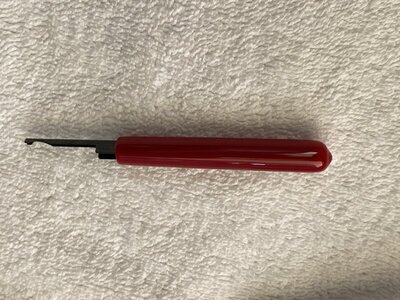
Anyone know how to open the jaws on this tool?
Squeeze it closed with some pressure; it should release at the bottom of travel. Or trip the manual rachet release lever (small tab just inside the pivot) while squeezing.

The jaw die does have a problem and likely needs replacement.
 
Squeeze it closed with some pressure; it should release at the bottom of travel. Or trip the manual rachet release lever (small tab just inside the pivot) while squeezing.

The jaw die does have a problem and likely needs replacement.
Thanks, that worked! I got it to open. I was not squeezing with enough pressure. Was worried that I might break it.

After opening, I can see there is flash on the TRIcrimp label side of the 45 upper jaw die that is creating the lopsidedness. 72RoadrunnerGTX knows ALL the technical terms, he is an awesome electrical wiring guru!

I better return the tool and not try to cut the flash off myself.. It is thick enough I will probably do damage to the die.
 
Having EXTREME difficulty getting the PP15 connectors inserted into the plastic housings. I have 18 gauge wires crimped onto them. The tool I bought from Powerwerx for insertion is as USELESS as TITS on a BOAR HOG.

That dumb tool just keeps slipping off the end of the connector every time I try to push it into the housing.. I’ve tried tiny flathead screwdrivers and they all slip off.

The 18 gauge wire/insulation is in the way and prevents the stupid tool from getting a grip on the end of the connector.

The 12 gauge wires are big enough that I could get enough force with my fingers on the wire to push the son of a bitch into the housing. If I apply the same force with my fingers to the 18 gauge wire I’m sure I’ll break the wires before the connector goes into the housing.

So far I’ve only managed to get one 18 gauge connector inserted (not using the tool). And I’m surprised the wire didn’t break off, I got lucky on that one.

How many HOURS will it take me to get those five remaining 18 gauge wires into their housings, if I ever get them in. WTF??

4EC987ED-CDBB-4AB9-A647-8DBCAA35A494.jpeg 8E4FB0B4-C923-4AA4-97C3-BC7315CDFB17.jpeg
 
Interesting, have never struggled to assemble those connectors the least bit even on the smallest of wires. Not familiar with the tool mentioned, I just used small jewelers’ flat blade screwdriver to push the terminal over the internal clip if needed.
 
I put my big “real” metal toolbox on the floor pan to support the housing while I push with “their” tool. With struggle I’ve managed to get two connectors inserted. I’ve got 3 left to go.. The next one, the tool didn’t push down straight and bent the wire over 90 degrees almost breaking it off.

In the future I’ll be trying some other type of connectors for 18 gauge or smaller wire because this is ridiculously difficult.. All this **** was ordered from Powerwerx too.. So it is not knock off stuff.

The left side of my neck hurts and is tight from the position I’m having to be in while struggling with these connectors. I tell ya working on this car is like fighting a war. It just wears you down..

And it is super annoying how every time I upload a landscape orientation photo directly from my iPhone 11 Pro, it appears upside down on this forum..

6AFF253B-E0B7-479E-B915-FA2CD55A4C4C.jpeg
 
I ultimately got all 6 of those damn 18 gauge connectors in their housings.. Unbelievable that it took a good 1.5 hours to insert 6 connectors. Getting the connectors out of the housings is no picnic either, as I accidentally put the wrong color housing on one of the 12 gauge wires. This was due to a previous owner extending a blue/white tracer wire with solid black, so I put the black connector on it instead of blue.

What was going on here, you might ask, extending the ignition run wire? A paranoid previous owner installed a hidden kill switch in this car. He used it to create an open circuit in the ignition run wiring. My forgetting about this dumb switch having only had the car for less than a week, caused me to flood the damn engine out last December, because I stupidly flipped the switch open and forgot I had done it. I cut all that **** out and threw that switch and all the crappy wire splicing that went with it in the garbage.

I also found another "connection" where the guy had only twisted two wires together with his fingers, then just put heat shrink tube over the twist.. I cut that entire lousy connection area off and threw it in the trash too. Add the hacked in Ford Voltage Regulator that used to be in the car and its equally lousy connections and it's really a miracle this car didn't burn up in a fireball of flames.
 
Last edited:
Furthermore, I have ordered a HIREV 7500 ECU and ballast resistor from Rick Ehrenberg. That should be here by next weekend.

I was hearing misfires at 2000+ RPM with the "Made in China" ECU box that was on the car. The USA made MP Orange box that I cleaned up, is untested and I prefer to start with a hopefully known "good" ECU.. If Ehrenberg's box works good only up to 5000 RPM, I'll be happy.. I'm not revving my matching numbers engine higher than that..
 
It's been over a month since I've updated my progress on the Chargeless Charger. Next weekend, I plan to run the engine and drive the car for the first time after starting all this wiring repair work. Which began in the first half of August.. Almost 4 months later..

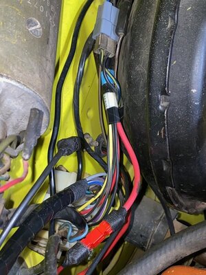
Replaced the engine harness with one from Evans Wiring Harnesses. Cut the 12 gauge black ALT BATT wire from the previous engine harness, and now have it running from the ammeter to the firewall. Cut the 12 gauge red Battery wire that ran from ammeter to the bulkhead disconnect, from an old engine harness that I found in a box, that came with the extra car parts.

Did NOT cut a new hole in the firewall. Instead, routed those through an existing hole in the firewall that is close to the bulkhead disconnect. Installed a rubber grommet that came from NAPA Auto Parts in the hole. This hole had 3 wires running up over the power brake booster. It now has the two charging wires running through it too.

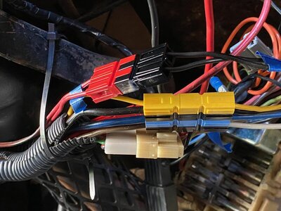
The two charging wires connect to the engine harness and headlight harness via PowerPole connectors. The bulkhead disconnect is completely bypassed now for these two wires.

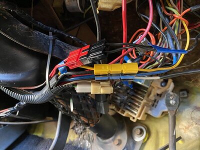
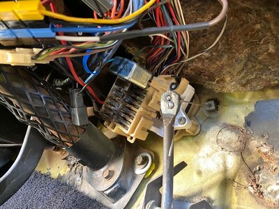
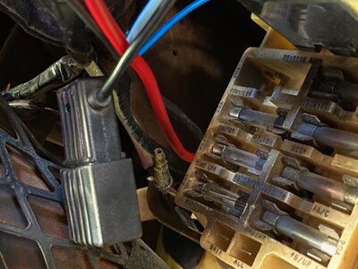
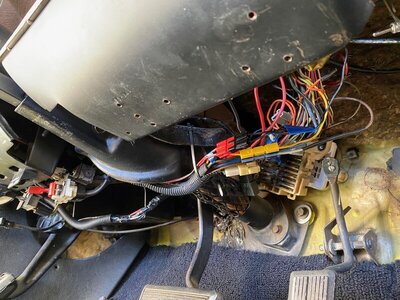
I have PowerPole connectors inside the car for 7 of the steering column wires, replacing the damaged Molex connectors for those wires.

Had to extend 3 wires (2 steering column wires and 1 ignition run wire with new packard connector to the bulkhead) by soldering new wire to them.

The PowerPole connectors don't connect to each other as solidly as I'd like. Doesn't take much force to pull them apart. I hope they stay connected and don't come apart on their own while I'm driving around.. I'm not fully sold on these connectors. Time will tell.

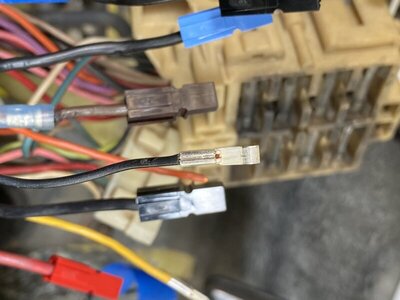
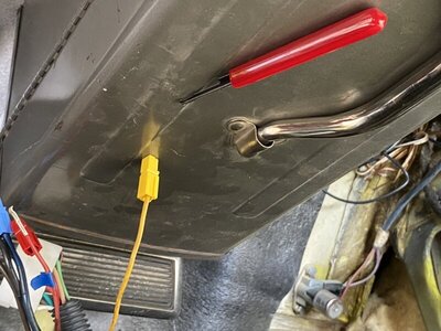
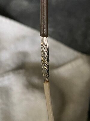
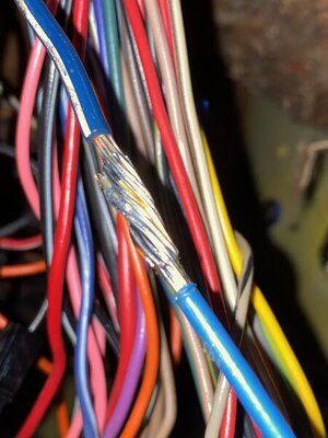
I added a couple photos of my solder extensions on a 14 and 12 gauge wire. The 16 and 14 soldering went well. The 12 gauge was a bitch, and didn't turn out as well as I'd like. The photos were taken before sliding the heat shrink tube over the connections and heating it, which I did with a hair dryer. The brown 14 gauge extension is what a good solder splice should look like. The blue 12 gauge solder is not as good. The thicker the wire the harder it was for me to get a good solder.

IMG_4668.jpg IMG_4669.jpg IMG_4670.jpg IMG_4463.jpg IMG_4467.jpg
 
It's been over a month since I've updated my progress on the Chargeless Charger. Next weekend, I plan to run the engine and drive the car for the first time after starting all this wiring repair work. Which began in the first half of August.. Almost 4 months later..

Replaced the engine harness with one from Evans Wiring Harnesses. Cut the 12 gauge black ALT BATT wire from the previous engine harness, and now have it running from the ammeter to the firewall. Cut the 12 gauge red Battery wire that ran from ammeter to the bulkhead disconnect, from an old engine harness that I found in a box, that came with the extra car parts.

Did NOT cut a new hole in the firewall. Instead, routed those through an existing hole in the firewall that is close to the bulkhead disconnect. Installed a rubber grommet that came from NAPA Auto Parts in the hole. This hole had 3 wires running up over the power brake booster. It now has the two charging wires running through it too.

The two charging wires connect to the engine harness and headlight harness via PowerPole connectors. The bulkhead disconnect is completely bypassed now for these two wires.

I have PowerPole connectors inside the car for 7 of the steering column wires, replacing the damaged Molex connectors for those wires.

Had to extend 3 wires (2 steering column wires and 1 ignition run wire with new packard connector to the bulkhead) by soldering new wire to them.

The PowerPole connectors don't connect to each other as solidly as I'd like. Doesn't take much force to pull them apart. I hope they stay connected and don't come apart on their own while I'm driving around.. I'm not fully sold on these connectors. Time will tell.

I added a couple photos of my solder extensions on a 14 and 12 gauge wire. The 16 and 14 soldering went well. The 12 gauge was a bitch, and didn't turn out as well as I'd like. The photos were taken before sliding the heat shrink tube over the connections and heating it, which I did with a hair dryer. The brown 14 gauge extension is what a good solder splice should look like. The blue 12 gauge solder is not as good. The thicker the wire the harder it was for me to get a good solder.

View attachment 1033951 View attachment 1033952 View attachment 1033953 View attachment 1033954 View attachment 1033955

Were you using a ROSIN CORE SOLDER (one designed for electrical/electronic soldering) and a light coating of ROSIN flux paste B4 heating the joint? Were you using a electrically powered soldering gun or plug in type of soldering iron and not a torch? The type of soldering iron/gun and the type of solder will make all the difference. NEVER USE AN ACID BASED FLUX OR SOLDER FOR ANYTHING ELECTRICAL ....it will corrode the connection. Correct materials can be obtained at your local ACE HARDWARE. Just my opinion of course.
BOB RENTON
Yes on all counts. I used rosin core solder, rosin flux, and a big Weller soldering gun (which I bought after I realized my soldering iron was woefully inadequate for the task). In the end, it cost me hundreds of dollars to fix the wiring issues in this car. And don't yet know if I've really actually fixed anything at all lol. Will find that out next weekend.

Had to re-read my posts in this thread. Looks like I didn't actually start the repair of the wiring until sometime after October 3rd. Before that it was all research, ordering tools/supplies, engine harness etc.

Haven't added it all up yet, nor have I added up all that I have spent on this life size scale model of a Super Bee over the past year that I've owned it. This weekend is my last chance to drive the model, before my 500 allotted mile insurance expires on it. I'm hoping to have driven at least 5 of those 500 miles before the expiration date. Might actually hit 1% of my estimated annual mileage for the first year!! Super excited!
 
Going to attempt to start the engine and drive the car on Sunday. Was distracted from this by the factory Stereo and Cassette Player/Recorder. Was going to try to test the Multiplex Stereo and if it works mount it back in the dash before installing the driver seat. But I'll probably just leave the radio out so I can test it when I have time. Getting the engine running and the car drivable is first priority. Will have to remove the seat again, to install the radio in the future.

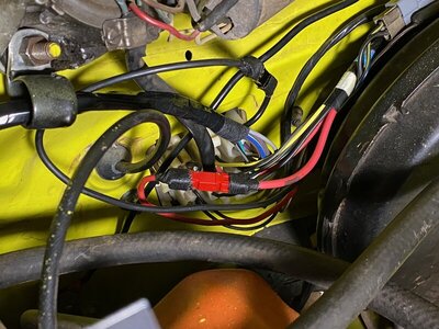
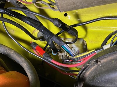
Added some more photos of my "new" steering column wiring work with the PowerPole connectors.

IMG_4818.jpg IMG_4819.jpg IMG_4820.jpg IMG_4821.jpg IMG_4822.jpg
 
Spent too much time screwing around mounting the Cassette Player base (with carpet and padding hiding the mounting holes, what fun), removing and reinstalling the rear seat and reinstalling the driver seat to run the engine and drive the car. All three things were a struggle and did not go smoothly. No surprise with that..

Car is still sleeping.. Gonna shoot for next weekend as drive the Super B Day. As of today, I have officially had the car for one year and it has moved under its own power exactly 3.8 miles.
 
Started the engine and drove the car this afternoon!! First time it ran and drove since August 2nd! It appears all my electrical work fixed the problem. The Charger is now CHARGING!!! Yeay!! :bananadance: And in more than one way!

I started the engine with my new INNOVA Professional Timing Light connected up. Before start up the light was showing 12.7 volts at the battery. After start up voltage increased to a maximum of about 14.7 volts. The ammeter gauge needle was on the + side, showing that the battery was charging! First time I've ever seen it on the + side. After letting the engine run for a while, and revving it up to 2000 RPM for a bit and backing off, the battery voltage settled down to about 14.4 to 14.5 volts. By this time the ammeter needle was right in the center of the gauge, showing no charge or discharge.

When revving to 2000 to 3000 RPM and holding it there, I am no longer getting occasional misfires that I used to get before all the wiring repair work. In addition to the repairs, I installed a Richard Ehrenberg HiRev 7500 ECU and supplied ballast resistor, to replace the no-name made in China ECU. I tend to think the ECU swap is what eliminated the engine misfiring.

When I took it for a drive, there were other noticeable improvements. First, the engine pulls harder than it used to. During the ENTIRE 3 mile drive, the ammeter needle stayed centered on the gauge. Before when stopped at a light or stop sign, pressing the brake pedal would push the ammeter needle over to discharge. With each flash of the turn signal, the needle would flick over to discharge side. Now, the needle stays centered when pressing the brake pedal or when the turn signal flashes!

This Charger is now on its way to becoming a SUPER DUPER BEE! :bananadance:After a year's worth of weekend work with the steering system and wiring I'm now finally able to DRIVE the car! It feels good to have a functional car, that can move under its own power. I'll be driving some more tomorrow. And will check the engine timing too.

Thanks for all the help you guys have given me here on the forum. @72RoadrunnerGTX thanks for your suggestions and showing me the PowerPole connectors. Those things actually seem to work!
 
So is prooved ( once more ) what the ammeter reading means and the reality on all of this.

with time you’ll notice is not bad the ammeter flickering a bit to - side specially with increased load requirements ( lights, wipers ) then a + reading proportional to the time and amount of - reading... everything of this according to RPMs, alt power capacity and keeping wiring in good conditions.
 
Auto Transport Service
Back
Top