• When you click on links to various merchants on this site and make a purchase, this can result in this site earning a commission. Affiliate programs and affiliations include, but are not limited to, the eBay Partner Network.

The Chargeless Charger

Damn, is just a simple way to say it!!!

The ammeter registers the charging load to the batt like if it was another sucker device when is discharged, and charge can't go faster or higher than the chemical process itself no matter how much extra amperes is the alternator able to source. Once the max capacity for the batt to get charged back has been reached, the extra alternator capacity won't push more amperes to it, then the ammeter won't "suffer" this extra alternator capacity. This is just what I try to explain.

Then we have all the theory to explain it with maths and chemical, true, but on the practical, this is what we are able to see on the ammeter.

And the ammeter charge reading will be getting reduced while the batt is getting charged back, still with the same alternator spining at same speed.

( for whatever scientific reason I'm not getting into )

Everything of this just while we don't have ANOTHER device getting sourced from batt side, because if there is, the ammeter will register this load too as a Charge reading which IS NOT A CHARGE LOAD, but THE reason to overload the ammeter with an incorrect charge load reading, and this is what is being happening FOR YEARS to then blame the ammeter
 
Last edited:
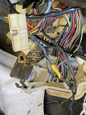
This weekend I did more inspection, digging deeper into the viper's nest of wires under the dash. Never realized how many ******* wires are under the dash of a 50 year old car.. Fist Full of Wires, and For a Few Wires More.. I saw the Good, the Bad and the Ugly wires in my car today.

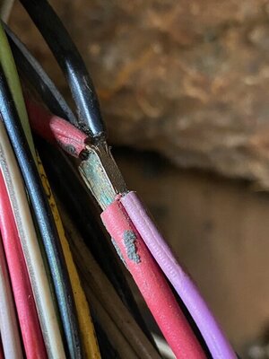
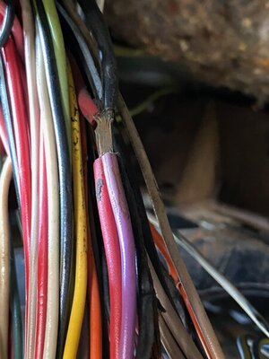
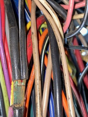
Alternator BATT wire is in sad shape from the bulkhead all the way up to the "splice". And what a weird looking junction splice it is. I tore the insulation off the junction (#1 diamond on the FSM schematic). The stiff black insulation material crumbled apart as a pulled it off with my fingers, leaving the bare junction. I wanted to see what was inside it. It looks like 6 wires all come together at one point, all interconnecting with each other. And it looks crappy. This is how the factory did this? Just clump the end of six wires together, overlapping each other, and cover it with some black stiff plastic like tape **** (don't know what this material is that crumbled apart)?

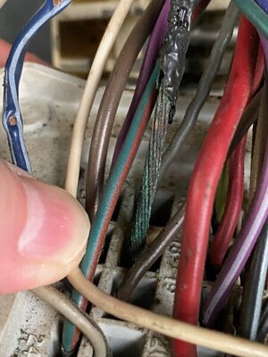
There is some green stuff on part of the outer surface of the junction. What is the green stuff? Alternator BATT wire down by the bulkhead is totally bare, no insulation left, and the wire strands are almost completely green, only a few small traces of copper color visible. Everything I'm showing you here was wrapped up inside black electrical tape. I had to take all the black tape off to see what the hell was going on inside this viper nest.

To fix this mess, I'll need to obtain:

1) new Bulkhead disconnect
2) replacement female packard connectors
3) new Alternator BATT wire (don't know the gauge)
4) new Ignition run blue w/white stripe (don't know the gauge. This wire was cut at the column connector with kill switch connected to it. I've removed the dumb kill switch, all it did was bite me in the ***, flooding the engine last December, when I flipped it in the kill position and days later forgot I had done so. New car with kill switch that you're not used too just keeps you the new owner from starting your own car.. As I crank and crank, wondering why the engine won't start, thinking it must not be getting fuel... So I pump the gas pedal before each crank, flood city... The average dumb car thief would flood your engine too doing this, so the whole kill switch placed in this circuit seems dumb to me.)
5) new engine harness, probably, instead of trying to fix the old one
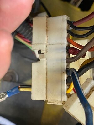
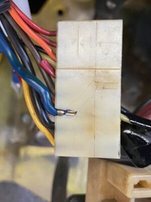
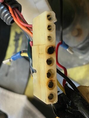
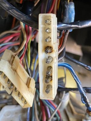
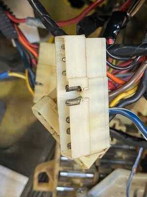
6) new Steering column male and female connector plastic pieces (I show photos of burned and misaligned connector pins on this one. Red wire has already been cut and bypassed due to a heat issue in the past with this lousy connector.)
7) new Steering column male connectors
8) new Steering column female connectors
9) new wire as needed for Steering column connectors.
10) tools to be able to remove install packard and bullet connectors

Can those Steering column connectors be bought separately? Without having to buy new Steering column and dash harnesses. What are those bullet shaped connectors called inside them?

The above shopping list will probably equal at least half the cost of a new dash harness. But, I just don't want to disassemble the whole dash and replace ALL the damn wiring underneath at this time.

And here comes my rant for the day..

I want to drive the car some within then next 6 months. After 9 months of owning this Super Duper Bee, I've had the pleasure of driving it a whole 3.8 miles! With the first half of that whopping mileage driven with the power steering belt disconnected. My Hagerty insurance policy was for 500 miles! When I chose mileage, I actually wondered if that would be enough to cover my intended driving lol. Thinking that I had just bought a driver that needed some things fixed on it. The insurance policy expires in 3 months, and i've used 3.8 of my 500 miles. And there is no ******* way this car is going any 496 miles in the next 3 months. More like 4.96 miles in the next 3 months, maybe..

IMG_3857.jpg IMG_3858.jpg IMG_3860.jpg IMG_3862.jpg IMG_3863.jpg IMG_3864.jpg IMG_3875.jpg IMG_3876.jpg IMG_3877.jpg IMG_3879.jpg
 
Damn I was to reply this along the day but forgot it. Midnight here and I'm at bed. Will do tomorrow. But a quick answer. Yes that splice is like that originally. It was electrically solded ( welded actually ) just like body panels are. This because use the tipical lead and soldering proces will take a lot of heat to get it propperly solded due the ammount of wires. I can't recall my car having a violet wire there, but sure a 71 and 74 could get diffs on that. Maybe is the horn relay feed. I know 73/74 are directly sourced from fuse box, but maybe 71/72 from there. I only can think on horn relay for Violet wire positive source.

and it uses to be taped with cloth/tar tape
 
Last edited:
green stuff... sulfates ( oxidized brass ) tipically found also on terminals. It can be cleaned with lemon juice or a bit of vinegar, then neutralize the acids with bakin soda solution.

Replace completelly that black wire between bulkhead and splice. Don't try to replace it from the main splice, but can be made a splice just right before the main splice to make a home lead solding splice and shrinking tube to seal it. You could also simply make the bulkhead bypass as we have talked in many threads latelly. MYSELF I would restore that wire AND ALSO will run the parallel path. but is just what I would make.

All main wiring network is made on 12 gauge

Bulkhead conectors are available new. You can reach them at Megapartsusa. Terminals are cheaper from any electrical supplier thought by bulk ( Packard 56 )

The wire between that splice and ignition switch plug is Red and gets up to a Standard Molex terminal .092". The ign switch harness terminals are called like that, Standard Molex, in two sizes .092" and .063". They are available from electric suppliers too just like Packards.

The blue wire can be replaced on the same way the black one between ign switch and bulkhead JUST that this wire gets a splice to feed the brake light at cluster and some other sources made from RUN ( ignition 1 ) circuit around the dash. This wire network should get a female packard plug hanging around from that circuit.

Ignition switch plugs are NOT AVAILABLE from regular places. MAYBE some harness manufacturer could get you those ? Try to get in touch with Evans wiring harnesses ( somebody posted once some vendor having male NOS ones thought ). The female end is included with ignition switches. They are useable yet thought. Well If available I'd try to replace, but myself being from overseas It makes me think everything is fixable and I try to fix anything before try to buy.

The red wire only runs between main splice and ign switch... thats easy to make too, just like the black wire between bulkhead and main splice

I can see your engine harness totally restorable and easy to make but that's just because I'm used to make that on my car. But at your own. Dunno your skills about wiring jobs.

The underdash harness is also easy to fix. It looks like a mess but is not really a mess, just 3 or 4 wires damaged and badly hacked up!

terminals removal... it can be done with any stuff you have around, but if you want a tool just search TERMINAL REMOVAL TOOL on google and will fin many options. I never have got any tool though. Molex can be tricky since they are round and the get two retaining tabs each... Packards can be done even with the tiny eyeglases or micrometric screwdrivers
 
Last edited:
OH... and all the wiring fix can be done in just one day... 2 if you want to make it with patiente. Not really hard or stressfull
 
I can see also a hack job made with a yellow and black wire into a female terminal ? dunno what could be that made for.

Also an orange wire? Orange wire is JUST dash dimmer lighting circuit. Maybe it got spliced from some extra aftermarket gauge ?

Or maybe is a red wire ( the red one originally running to ign switch plug )
 
Last edited:
I can see also a hack job made with a yellow and black wire into a female terminal ? dunno what could be that made for.

Also an orange wire? Orange wire is JUST dash dimmer lighting circuit. Maybe it got spliced from some extra aftermarket gauge ?

Or maybe is a red wire ( the red one originally running to ign switch plug )
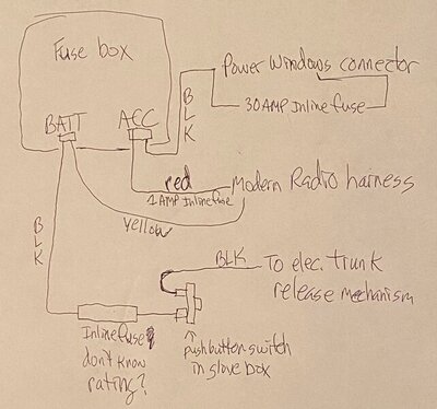
The wires you are referring to are for accessories added by previous owners: modern stereo radio/CD player, power windows (conversion kit installed in the two doors), electric trunk release.

I have removed the modern radio/cd player which was mounted in the factory Cassette Player housing. I also removed the factory AM/FM Multiplex Stereo from the dash (it only had its red power wire connected, the other 4 wires were not connected to anything).

I have added a drawing that I made showing how these 3 accessories were wired up. The switch for the electric trunk release was located inside the glove compartment. The Yellow wire on BATT terminal to radio was probably getting a small current direct from Battery to retain station presets in its memory.

IMG_3882.jpg
 
The 3 wires below the #1 splice/junction are: Black (Alternator BATT), Violet (Horn Relay), Red (BATT terminal on fuse box). The 3 wires above the #1 splice are: Black (to Ammeter gauge), Black w/white stripe (to Headlamp switch), Red (Battery on steering column molex connector).

I could try to clean that splice with white vinegar, then put some baking soda on it to neutralize. Or, I could use DeoxIT on it, and the packard connectors that I will not be replacing. I only plan to replace the fried ones.

"Simple contact “cleaners” wash away dirt, dust, and grime, but prove ineffective at removing oxidation and surface sulfides. The only true method of eliminating oxidation and surface sulfides is by chemical action and reaction. This is one aspect separating DeoxIT® products from other products, putting it in a class by itself."
 
Ok, the original trunk release when optioned was sourced from that place too.

I'm aware about the splice wiring, just the violet is new to me there. Since 72 that was changed to a fuse box source. I have the 71 diagram, but didn't checked it LOL, was just talking by memory.

About the packard terminals, yes I'd make the same. I made it on my car in fact and a friend's Dart. Cleaned the good ones, replaced the damaged ones.

I never have got really great results with contact cleaners. So went with brush and soap for grease removal, then vinegar for what it rest. I even used a tiny "rolled" sandpaper piece ( whatever fine grit ) to clean into the female packard ends.
 
Last edited:
The connectors to the ignition switch are Moldex connectors... Their were made in three sizes, the small ones .062 aren't used on our cars... The medium ones .093 are the smaller ones used at the turn signal switch and on the small wires of the ignition switch.... The big connectors are very hard to find, I seem to recall them being .131 or something close to that.... Chrysler used them for the main power connections to the ignition switch... I found a single package of them 5+ years ago through Digi-key but thats all they had...

the .093 connectors are easy...

https://www.amazon.com/Molex-Connec...WC4MZ109SMS&psc=1&refRID=WK7V15GKGWC4MZ109SMS
 
Yeap, sorry about the size. I live into metric world so try to imagine imperial measurements is Sometimes hard to me.

However I think the ones used on ign switch are 0.093"? That's allmost 3 millimeters!!! That's around the size I recal at least. So the turning switch ( and smallers on ign switch is 0.062" )

.131 is more than 4 mm! That's definitelly not the size for them! not that I can recall. 4 mm is around the thickness of the white plug

Somebody dunno if on this board or some other actually had to make the same fixing job and got those 0.093 for his ign switch! ( Moparfiend or something like that on his 70 RR I think? )
 
Last edited:
I'm not seeing any 8 wire Molex connector like the stock connector on the car.

I wonder if these battery batter XT60 connectors would work as a replacement, using 4 sets of male/female, to replace the entire stock connector: https://www.amazon.com/OOOUSE-XT60-Connector-Pairs-pairs/dp/B005FAPYXS

description says, "Made from high-temp Nylon and gold plated spring connectors, the XT60 ensures a solid high-amp connection, perfect for applications up to and beyond 65A constant."
 
I'm not seeing any 8 wire Molex connector like the stock connector on the car.

I'm telling you publicly they don't exist. Not even on specific automotive terminals and plugs suppliers which sometimes get available the weirdest ones, HOWEVER they must be available somewhere because the harnesses manufacturers get those from somewhere. And ignition switch manufacturers get the female ones.

I would try to get in touch with Evans harnesses just in case they can supply them.

Any other aftermarket solution is a matter of preference. I know 72RoadrunnerGTX made its own setup with heavy duty conectors which can be stacked on, but even I have seen them several times, I allways forget how they call LOL.
 
Yeap, sorry about the size. I live into metric world so try to imagine imperial measurements is Sometimes hard to me.

However I think the ones used on ign switch are 0.093"? That's allmost 3 millimeters!!! That's around the size I recal at least. So the turning switch ( and smallers on ign switch is 0.062" )

.131 is more than 4 mm! That's definitelly not the size for them! not that I can recall. 4 mm is around the thickness of the white plug

Somebody dunno if on this board or some other actually had to make the same fixing job and got those 0.093 for his ign switch! ( Moparfiend or something like that on his 70 RR I think? )

Screen Shot 2020-09-02 at 12.10.55 AM.png


You tell me what size they are.....
 
I'm not seeing any 8 wire Molex connector like the stock connector on the car.

I wonder if these battery batter XT60 connectors would work as a replacement, using 4 sets of male/female, to replace the entire stock connector: https://www.amazon.com/OOOUSE-XT60-Connector-Pairs-pairs/dp/B005FAPYXS

description says, "Made from high-temp Nylon and gold plated spring connectors, the XT60 ensures a solid high-amp connection, perfect for applications up to and beyond 65A constant."

Those are used for R/C cars, I doubt they carry the current load that the ignition switch connectors see...
 
Those are used for R/C cars, I doubt they carry the current load that the ignition switch connectors see...
the current rating for those R/C connectors is 65 Amps continuous. The current rating on the Molex connectors Nacho linked to is only 17 Amps.

65 Amp connectors should even handle Triple Black 73 "Anti-Ammeter" guy's 250 Amp alternator and his Mad Max Fury Road Stereo system!
 
Last edited:
Yeap, and .131 is allmost 3.5 mm. But I know somebody already made this job and got the terminals for it
 
Auto Transport Service
Back
Top