• When you click on links to various merchants on this site and make a purchase, this can result in this site earning a commission. Affiliate programs and affiliations include, but are not limited to, the eBay Partner Network.

The Chargeless Charger

Yeap, and .131 is allmost 3.5 mm. But I know somebody already made this job and got the terminals for it

A little less
Screen Shot 2020-09-02 at 12.29.06 AM.png
 
Well I'm telling not sure, but .131 sure sounds huge for me.
I have calipers and a micrometer. When I remove that 8 pin molex connector from the car I will measure those connectors and tell you exactly what diameter they are..
 
the current rating for those R/C connectors is 65 Amps continuous. The current rating on the Molex connectors Nacho linked to is only 17 Amps.

65 Amp connectors should even handle Triple Black 73 "Anti-Ammeter" guy's 250 Amp alternator and his Mad Max Fury Road Stereo system!

And, if I use them, I could have a 1:1 Scale R/C Super Bee!! How cool is that?

I keep staying up late researching all this stuff.. I gotta get to bed and get some sleep..
 
This is the guy who replaced his terminals

https://www.forbbodiesonly.com/mopa...ch-and-ignition-switch.196473/#post-911633239

BTW, making their website product search found Molex only have 0.062 and 0.093. So or they are 0.093 or the ign switch manufacturers and repro harness manufacturer get those terminals ( if larger ) from any other manufacturer.
IMG_1088.jpg


Need to note I'm not saying I'm right, just posting what I find.

Looking at a rule, it seems is correct the ign switch could be larger than 0.093" however dunno If the diameter measurement is for the male or the female.
 
Last edited:
about Molex standard pins:

https://en.wikipedia.org/wiki/Molex_connector

just 3 sizes per WP info, but one is a middle one between the ones being discussed.

The AMP conector used on PC ATX power is 0.093 ( per that info ). I got those from Radio Shack once to fix my tail light connection on trunk ( using just the terminals not the sockets from the kit ).

It seems the diameter must be measured at male pin
 
Anderson Power Poles, 45 amp rating, if you replace the Molex connectors with new ones, they will fail again.
20181208_130458.jpg
 
Last edited:
And get the power windows off the ACC tap at the fuse box, that added load is routed through the ign switch/connectors as diagramed, install a relay.
 
It could make a mix of Anderson Power Poles for all the 12 gauge wires and use a 3 way molex plug for the existant smaller molex terminals ( ign switch sensor wires and shifter light wire )

s-l300.jpg
 
Anderson Power Poles, 45 amp rating, if you replace the Molex connectors with new ones, they will fail again.
View attachment 996565
Never heard of these and know nothing about them, but they look like they would do the job.
https://www.andersonpower.com/us/en/resources/PowerPoleResourcesPage.html

I'm going to guess that the ones shown in your photo are PP15/45 Standard Housings? I see Tin and Silver plated power contacts. Male and female housings. Male and female contacts. Yours look like they interlock. Hopefully these things can be obtained from one of my local electronics stores.

I'll have to watch some videos on how to use these things. Did you solder your wires to the contacts, or clamp them on?
 
And get the power windows off the ACC tap at the fuse box, that added load is routed through the ign switch/connectors as diagramed, install a relay.
I've never installed a relay in my life.. I read about using them for headlights about a month or two ago, but don't know anything about how to actually install them.

I see the factory manual shows a schematic for power windows with Window Lift Safety Relay and Window Lift Safety Circuit Breaker modules that plug into the fuse box. First time I've ever owned an old car that had power windows, and they are not factory.

I believe it may have been the same kit that Steve Dulcich installed in a 3rd Gen Charger in this old Hot Rod Magazine article: https://www.hotrod.com/articles/mopp-0302-installing-power-windows-in-a-dodge-charger/

He also connected them to the ACC terminal on the fuse box, in the article! So Dulcich doesn't know what the hell he his doing apparently.. Probably neither does Freiburger!

LOL, Steve must have installed mine! That might be my Charger that is in the article! Haha! Mine has those same GM switches and ACC terminal connection! Or Maybe the installer used that article as a guide!
 
Never heard of these and know nothing about them, but they look like they would do the job.
https://www.andersonpower.com/us/en/resources/PowerPoleResourcesPage.html

I'm going to guess that the ones shown in your photo are PP15/45 Standard Housings? I see Tin and Silver plated power contacts. Male and female housings. Male and female contacts. Yours look like they interlock. Hopefully these things can be obtained from one of my local electronics stores.

I'll have to watch some videos on how to use these things. Did you solder your wires to the contacts, or clamp them on?
Yes, PP15/45 series pictured. They are crimped, no genders, same connectors used for each side. three different connector sizes for various wire sizes in that series. Yes, the housings can be interlocked.
Get them from this place, careful there are knock-offs of these out there.
20200903_083602.jpg
 
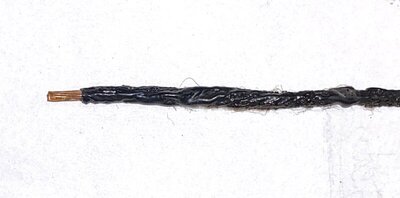
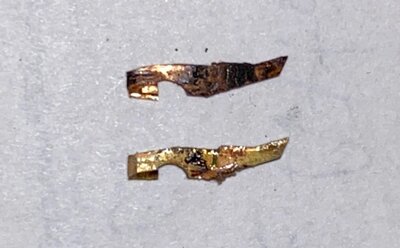
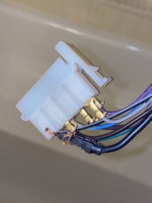
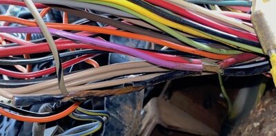
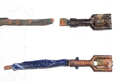
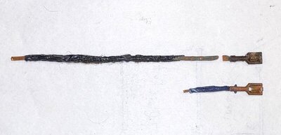
Back to the wiring.. Did a little surgery today. Extracted two pieces of the two damaged wires and their female packard connectors. Alternator BATT connector looks like it was cremated, cooked beyond "well done". Ignition run is about "medium well". Alt BATT insulation is a melted mess about 6 inches up the wire. I don't have much Alt BATT wire remaining below the splice junction (that still has insulation intact). It was mostly torn away up near the junction, as I found it. The wire strands look good up there though, no green **** on them.

Alt BATT wire is 12 gauge, Ignition run wire is 16 gauge, as measured with my Dad's old wire strippers.

It was difficult to remove the female connectors with my available screwdrivers. My 1.4mm flat head worked the best, but even it won't release the red wire that runs up to the Ammeter gauge. Can't get that one out of the bulkhead body.

I had to cut the two fried male connectors on the engine harness, but the Ignition Run wire is still stuck inside the plastic connector and won't come out. All the unfried male connectors came out rather easily.

How should I attach new 12 gauge black wire to the Alt BATT below the junction? Try to solder? Or some kind of crimped connector? I don't have much insulated wire left up there, so whatever I do, I think I have one shot at doing it.

Also, what should I use to cover up and insulation the junction itself? A couple weeks ago I broke whatever was insulating it away with my fingers to see what the inside looked like. The black stuff that was on there just crumbled away..

IMG_3968.jpg IMG_3970.jpg IMG_3971.jpg IMG_3976.jpg IMG_3951.jpg IMG_3952.jpg AlternatorBATTSplice.jpg
 
It looks like the 12 gauge female Packard 56 connector part, where the wire is crimped on, is larger in diameter than the same connector that is attached to the 16 gauge wire. Are the wire crimp ends of the Packard 56 female connectors different diameters for different wire gauges? I need to figure out what specific connectors I need to replace these two.
 
It looks like the 12 gauge female Packard 56 connector part, where the wire is crimped on, is larger in diameter than the same connector that is attached to the 16 gauge wire. Are the wire crimp ends of the Packard 56 female connectors different diameters for different wire gauges? I need to figure out what specific connectors I need to replace these two.

Yes, lots of vendors sell the connectors....
 
Sold the wire is quite enough after a good twist strands job. Use shrinking tube to seal it after soldering job it would be a good idea. Even double shrinking tube for extra isolation replicating the wire cover thickness

Althought on this link they use silicone to replicate the original wire cover and make it water proof and just one shrinking tube to seal it. I still would use dual shrinking tube. Specially if some strand is able to cut the tube after get shrink. Unless you trim it out

https://www.wikihow.com/Solder-Wires-Together

For the splice, originally was used cloth tape. It should be available at shops? I guess, I have seen them available on the web quite often, but can't put my word on that if available at regular shops around in USA. I have used regular electrical tape anyway on my car ( never have seen the cloth tape being sold in Venezuela. Maybe it is available searching further but never have seen it ). You could use also self bonding tape for it. Electrical tape and self bonding tapes ( depending on the application ) is aprooved to be used and regularly used in high tension lines anyway. Dunno why cloth tape was used there back in the days. Afraid of some heat on splice melting the tape? Dunno.

Terminals are the same, but provision for the crimping wire changes according to the wire gauge rate is made for.

Wire coming from ign switch for the run circuit wire, should be 12 Althought it becomes into 14 or 16 into engine bay. As mentioned before, it gets some splice in the run to feed an extra source for some accesories and the cluster brake light.

Replace the connector if you can get out the terminal in there. Several seller got them and all at same price rate ($15), but megapartsusa use to be a very trustable and nice source. One of the safety locking tabs is broken anyway. It's a shame because it looks to be new!
 
Last edited:
I've never installed a relay in my life.. I read about using them for headlights about a month or two ago, but don't know anything about how to actually install them.

pretty much straight up and can be done on a nice way to install them hidden and protected from the environments, like I made, installing them on back of the kick panel area. I didn't want visible relays on engine bay neither cut the harness after a rebuilt job. I made it is simply relocating the terminals here and there. I took the power for relays from ammeter stud ( black end to take from alternator side ), but sure I also have a parallel path for my charging system to sabe bulkhead terminals, and an upgraded alternator.

Will post the diagram later on what I made. Of course I also upgraded to halogen sealed beams when making this job. Previous owner had the headlight harness hacked up with a giant relay attached on top of inner fender and was using replaceable halogen bulbs on headlight screens. The chrome inside was all peeled up, because these setup wasn't a sealed system for the bulbs.
 
here the diagram of what I made to install bosch kind relays. They can be 4 or 5 pins ( the 5th pin is labeled 87a which is not used on this case since is normally closed circuit )

30 is the batt source
85 is ground
86 is the trigger. On this case is triggered from dimmer floor switch
87 is the output to headlights, being sourced by the 30 terminal when relay is triggered up

relay upgrade on kick panel area CORRECTEDa.jpg


I removed the terminals going to dimmer switch to be conected on the relay ( using a socket for it ) and replaced the missed wire at floor switch with a same color wire jumping out the dimmer sitch to the rigger in signal to relay. Of course 2 female packard switchs on the jumper wire, to be able to reinstall on sockets. Then retapped the harness

This makes to look like this ( I don't have headlight relay pics handy, but made the same for the A/C blower system ) :

from the distance seems to be an untouched harness:

Imagen226a.jpg


but if you pull the harness out will find:

Imagen227a.jpg


This relays are hold by the A/C box bracket ( hence the U cut on one of them, to be able to slide it up into the bolt and tight the nut ) and relay sockets are interlocked

I used 6 relay setup on a power line spliced from the ammeter stud. 2 for headlights and 4 for the A/C Blower system. On pic is shown the low and mid speeds. The high and Heater speed relays ( yes, A/C cars get an exclusive heater speed lower than the A/C lower speed ) are attached around brake pedal brakes bracket setup.

relay upgrade underdash2.jpg


The relays for blower was made because on 73/74 the blower lever switch is not able to hold the blower load and ALWAYS gets melted the plug and gets hot enough the switch lever to burn your finger when selecting some speed. I replaced the blower switch plug at least 2 times in 4 or 5 years. 71/72 are a bit diff on this because the switch gets a pigtail attached not a plug straight to the switch, so the plug doesn't melt. Can't tell if switch gets also hot.

This made to not cut any wire around, just removing terminals from original connectors. Clean and easy to get it back

Originally headlight switch gets a breaker built inside ( never have seen that but experts here confirm that ), to protect the headlight system, which is out of the fuse box protection. The relay makes allmost unusefull this built in breaker because headlight switch won't be getting anymore the headlights load, so for extra safety the power line ( 30 ) should be protected somehow. I used a 16 gauge fuse link because was the best what I have in hands, but better if using a safety breaker ( I will upgrade that someday ). Regular fuses work too, BUT, they won't hold a peak and for this kind of stuff is better to have something able to hold peaks.
 
Last edited:
"Regular fuses work too, BUT, they won't hold a peak and for this kind of stuff is better to have something able to hold peaks."
INCORRECT ASSUMPTION....Perhaps, you should review a fuse application guide book (published by Buss or Littlefuse or CarboneFerraz-Amptrap) as there are several types of TIME DELAY fuses, designed to allow high inrush current to pass thru, yet protect against sustained OVERLOAD confitions and some manufacturer's offer designs that offer current LIMITING as well as time delay features. Perform your due dilligance ahead of time...
BOB RENTON
 
Yes, PP15/45 series pictured. They are crimped, no genders, same connectors used for each side. three different connector sizes for various wire sizes in that series. Yes, the housings can be interlocked.
Get them from this place, careful there are knock-offs of these out there.
View attachment 996928
The 3 connectors have different amp ratings, for different wire gauges.
  • 15 Amp (SKU: 1332) is designed to receive 16, 18 and 20 gauge wire.
  • 30 Amp (SKU: 1331) is designed to receive 12, 14 gauge wire.
  • 45 Amp (SKU: 261G2) is designed to receive 10 gauge wire.
In the photo of your installed connectors you mention a 45 Amp rating. Did you use the 45 Amp PP45 connectors on the 12 gauge steering column wires? I see the manufacturer is stating 12 gauge wires should use the 30 Amp PP30 connectors. None of those steering column wires are 10 gauge (I measured them with my wire stripper tool). The smaller column wires are 16 gauge, so 15 amp PP15 size.
 
Someone had sourced power for the electric choke, on my Holley carb, from the field terminal on the alternator where the blue w/white stripe wire connects. Is this a correct or incorrect place to draw power for an electric choke? If it is incorrect, where should power be sourced for the choke?
 
Yes is correct.. that’s the RUN circuit.

on later models ( 73 and on ) the choke used a control unit to regulate the voltage to the manifold mounted choke spring. Of course these cars got the source built in harness, but it was spliced from same wire on the run to the alt field

6046787-choke-jpg.jpg
 
Auto Transport Service
Back
Top