Love that pistol grip 747Mopar . . . and the first half of the tunnel looks great ! Even better than the stock one ! !
You are using an out of date browser. It may not display this or other websites correctly.
You should upgrade or use an alternative browser.
You should upgrade or use an alternative browser.
Viper T56 install
- Thread starter 747mopar
- Start date
HYRDGOON
Well-Known Member
- Local time
- 12:33 AM
- Joined
- Apr 20, 2013
- Messages
- 3,372
- Reaction score
- 2,745
- Location
- Breslau, Ontario, Canada
Is that pistol grip something you milled Devin or did that come with the package? X2 on what Kahn said it's nice!
Goodluck (not like you needed it) with beating on more metal today! hahaha
Goodluck (not like you needed it) with beating on more metal today! hahaha
Is that pistol grip something you milled Devin or did that come with the package? X2 on what Kahn said it's nice!
Goodluck (not like you needed it) with beating on more metal today! hahaha
That's the same Titanium one that my dad milled out for my auto.
- - - Updated - - -
Finished up the cutting, grinding, bending, welding and drilling part of the job today. She's all patched back up, I'll come back and clean it up, seam seal it and get it back in black next time.
Here's more pattern making.
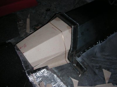
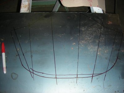
Test fitting.
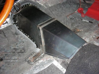
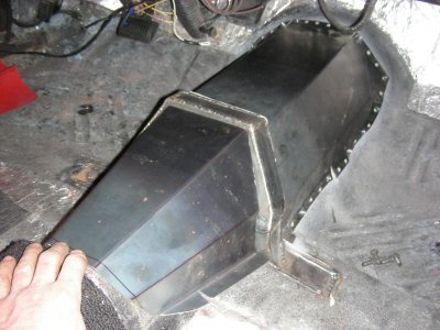
Checking for tight spots before removing the tranny again. As you can see the reverse light switch will need a pocket put in the floor in order to be able to hook it up and I only have an 1/8" on the driver side by the tranny bolt flange (BFH will fix that). I tell you not having a tranny jack sucks, I laid under the car like I have been and removed all of the tranny bolts while holding the tranny with the other hand. Once they were all out I got a good hold and slid it back off of the dowels and PLOP, it landed on my chest hard enough it made me fart haha.
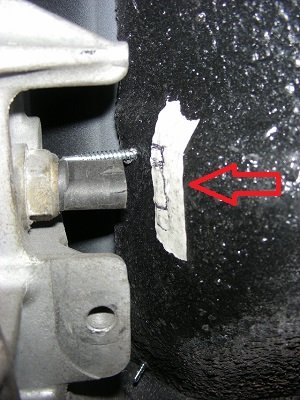
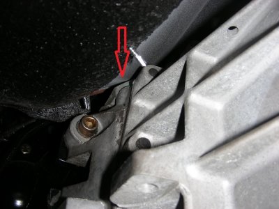
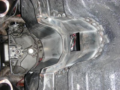
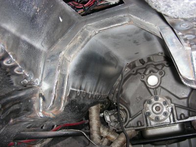
Here's the finished tunnel, console still fit's.:headbang:
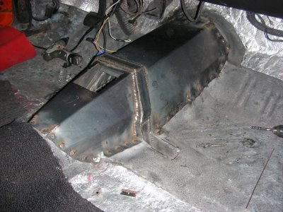
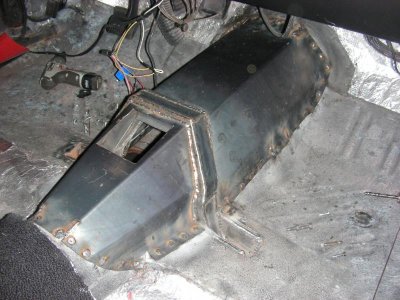
And from underneath.
- Local time
- 12:33 AM
- Joined
- Oct 16, 2014
- Messages
- 27,941
- Reaction score
- 66,030
- Location
- Salisbury, Vermont
very cool, nice neat work. Congrats!
Hey 747 Mopar . . . sorry that you got "winded" in the process . . . LMAO . . . the things we do for our hobby ! ! !
Looks great - I didn't know you were building a 2nd room for the kids to play ? ? That thing is HUGH ! !
I know, to fit the 6-speed ! ! !
Looks great - I didn't know you were building a 2nd room for the kids to play ? ? That thing is HUGH ! !
I know, to fit the 6-speed ! ! !
It looks bigger than it is and you really couldn't make the forward part any smaller (it's pretty tight in there). The rear part could be a good bit smaller but I wanted to keep the reverse lock out and I accidently put a big hole in the tunnel trying to remove a previous mount so I just made it big enough to patch everything.
HYRDGOON
Well-Known Member
- Local time
- 12:33 AM
- Joined
- Apr 20, 2013
- Messages
- 3,372
- Reaction score
- 2,745
- Location
- Breslau, Ontario, Canada
Nice clean work as always! Be thankful it was just a fart! lmao
Also glad to hear the console still fits! One less thing to deal with
Also glad to hear the console still fits! One less thing to deal with
6speedGTX
Well-Known Member
For anyone interested in doing this swap, I stumbled across this module to control the reverse lockout solenoid using the VSS signal similar to how they were controlled from factory.
http://www.samocoind.com/T56MODULE.html
http://www.samocoind.com/T56MODULE.html
HYRDGOON
Well-Known Member
- Local time
- 12:33 AM
- Joined
- Apr 20, 2013
- Messages
- 3,372
- Reaction score
- 2,745
- Location
- Breslau, Ontario, Canada
For anyone interested in doing this swap, I stumbled across this module to control the reverse lockout solenoid using the VSS signal similar to how they were controlled from factory.
http://www.samocoind.com/T56MODULE.html
For $100 it's not a bad investment at all for a simple solution!
Mr.SpeedFreak
Well-Known Member
Damn! That trans tunnel looks gorgeous man :icon_thumleft:
Cheaper than having a T56 rebuilt to replace chomped up gears I'm sure haha
For $100 it's not a bad investment at all for a simple solution!
Cheaper than having a T56 rebuilt to replace chomped up gears I'm sure haha
Not as much progress tonight. Since I planned on making 2 sets of throw out spacers (if needed) I figured I'd compare our clutch setups for installed thickness so I wouldn't have to check them both on the car. I placed the flywheel on a flat plate of steel and installed my clutch and measured from the pressure plate fingers to the plate then the same with Goons dual friction setup...............What I learned was they were both 3 1/8" on the button and I need to figure out how to make mine look like a dual friction so Goon takes the wrong one haha (it's pretty sweet). With that out of the way it was time to start checking clearances.
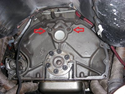
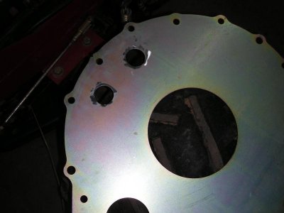
First order of business was this, the back of the blocks are machined smooth even the camshaft area where the 2 oil galley plugs are meaning if they stick out at all you need to allow for that in the plate. I just painted the heads of the plugs and installed the plate to get the locations and hole sawed them out.
With that done it was on to mounting the flywheel to check the bell housing run out (making sure the bell housing register is true to the crank centerline). On the TKO bell housing the bore in the bell is what locates the tranny much like a wheel fitting on the hub of an axle but on the T56 it's located by dowel pins meaning you cannot do it the same way which is where the night went to chit (briefly). Reading the instructions to see how they propose accomplishing this revealed that you have to pull the front plate off of the tranny. I looked at the tranny and thought just how in the hell am I supposed to put a dial indicator base threw that dinky hole, get an indicator mounted and read off of such a little race? Wasn't as bad as I thought (the bell housing comes with instructions on how to do this).
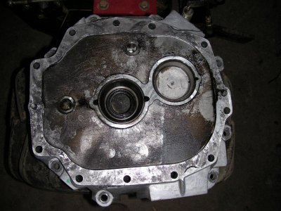
Here's the plate remove, much to my surprise it came off very easily with no surprise parts falling out. The hole in the center is where the indicator needs to come threw to read off of the bearing race.
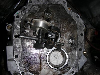
Here's the plate (front of tranny) bolted on the bell with the indicator mounted on the center of the flywheel manipulated to get a reading. This is allot of fun to do by yourself! Since you can't watch it as you turn it by yourself taking note of the starting point will allow you to double check that the indicator doesn't move on you (it should read the exact same as it did after a full turn and if it doesn't something moved on you, do it again). I turned it about an 1/8 of a turn at a time checking the reading all the way along (because of the way the indicator had to be mounted this meant using a mirror to see it). The total out of whack reading was .003", since your checking for run out you split that in half to .0015" with an allowance of .005 so we are in really good shape here.
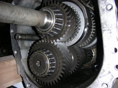
At least this gave me a peak inside of the tranny and boy does this thing look good so a little piece of mind was gained.
First order of business was this, the back of the blocks are machined smooth even the camshaft area where the 2 oil galley plugs are meaning if they stick out at all you need to allow for that in the plate. I just painted the heads of the plugs and installed the plate to get the locations and hole sawed them out.


With that done it was on to mounting the flywheel to check the bell housing run out (making sure the bell housing register is true to the crank centerline). On the TKO bell housing the bore in the bell is what locates the tranny much like a wheel fitting on the hub of an axle but on the T56 it's located by dowel pins meaning you cannot do it the same way which is where the night went to chit (briefly). Reading the instructions to see how they propose accomplishing this revealed that you have to pull the front plate off of the tranny. I looked at the tranny and thought just how in the hell am I supposed to put a dial indicator base threw that dinky hole, get an indicator mounted and read off of such a little race? Wasn't as bad as I thought (the bell housing comes with instructions on how to do this).
Here's the plate remove, much to my surprise it came off very easily with no surprise parts falling out. The hole in the center is where the indicator needs to come threw to read off of the bearing race.

Here's the plate (front of tranny) bolted on the bell with the indicator mounted on the center of the flywheel manipulated to get a reading. This is allot of fun to do by yourself! Since you can't watch it as you turn it by yourself taking note of the starting point will allow you to double check that the indicator doesn't move on you (it should read the exact same as it did after a full turn and if it doesn't something moved on you, do it again). I turned it about an 1/8 of a turn at a time checking the reading all the way along (because of the way the indicator had to be mounted this meant using a mirror to see it). The total out of whack reading was .003", since your checking for run out you split that in half to .0015" with an allowance of .005 so we are in really good shape here.

At least this gave me a peak inside of the tranny and boy does this thing look good so a little piece of mind was gained.

Mr.SpeedFreak
Well-Known Member
Not bad runout at all! I gotta laugh when I see some manufacturer recommended runout tolerances that look huge to me, especially with the factory 4 speeds. I was doing OD grinding at work today held to within about .0002, which is normal for us unless I'm just pre-forming something. Anyway, dang that thing looks even nicer on the inside haha!
HYRDGOON
Well-Known Member
- Local time
- 12:33 AM
- Joined
- Apr 20, 2013
- Messages
- 3,372
- Reaction score
- 2,745
- Location
- Breslau, Ontario, Canada
Great step by step instruction. All these pics and procedure will definitely help with mine in the future and some others on here for sure. I'm pretty sure you can just mock up another disc with Cardboard and tell me that's my dual friction I'm likely to fall for it! Hahaha
What are your thoughts on the reverse lockout module?
What are your thoughts on the reverse lockout module?
Great step by step instruction. All these pics and procedure will definitely help with mine in the future and some others on here for sure. I'm pretty sure you can just mock up another disc with Cardboard and tell me that's my dual friction I'm likely to fall for it! Hahaha
What are your thoughts on the reverse lockout module?
I like one of the posters idea (sorry can't remember who posted it) of wiring it into the brake lights or I even thought about a button on the shifter. I haven't really looked into it yet but as long as it's just a simple 12V solenoid I'll be doing one of those 2 options.
HYRDGOON
Well-Known Member
- Local time
- 12:33 AM
- Joined
- Apr 20, 2013
- Messages
- 3,372
- Reaction score
- 2,745
- Location
- Breslau, Ontario, Canada
Right! I think it was 6speedGTX who suggested that... forgot all about it! Good way to save $100
- Local time
- 12:33 AM
- Joined
- Oct 16, 2014
- Messages
- 27,941
- Reaction score
- 66,030
- Location
- Salisbury, Vermont
I feel for you on the whole getting the indicator in place and being able to read it as well. Used to get readings on all kind of bearings and shafts, flight control surfaces etc. I've had to use a mirror many times and be a contortionist to even get close enough to see anything.
Another good night! Finished a couple welds, added a pocket for the reverse switch, sealed it with seam sealer, got it all painted with bedliner, installed the flywheel and clutch and checked the T.O bearing clearance.
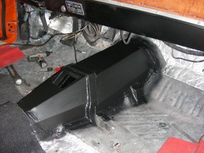
Here's the sealed and painted tunnel.
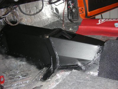
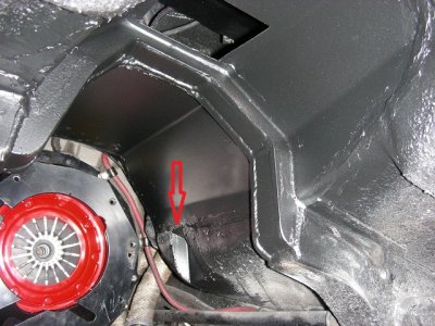
Here's the pocket to allow room to plug in the reverse light switch.
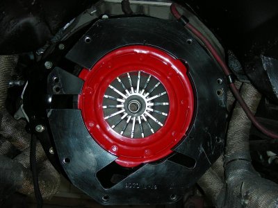
A pic of the bell, flywheel and clutch installed.
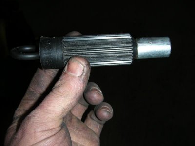
This was a minor bummer, the alignment tool has the wrong pilot Dia so a sleeve was made to deal with that only to find out Goons clutch came with a selection of different ones (go figure).
Here's a topic (whether or not you need to shim the T.O bearing) of debate and now I know why. The Keisler instructions that came with the TKO I had called for 1/4"-1/2" clearance but my McLeod clutch calls for 1/8"-1/4" (I'll go with McLeod's recommendation).
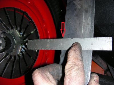
This is a very quick and easy thing to check especially if you have 2 bell housings laying around (thank you Goon). Start by installing your flywheel, clutch and bell housing then lay a straight edge across the back of the bell and measure the distance to the fingers like in the pic (2 7/8").
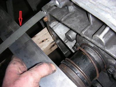
Now push the T.O. bearing all the way in bottoming it out and lay a straight edge across the T.O. Measure from the straight edge to the tranny mounting surface like in the pic (2 1/2"). It's important to measure back to the tranny mounting surface on both sides to be sure your holding the straight edge square (measurements should match if holding it straight). Do the math and I've got 3/8" which is great by Keislers instructions but an 1/8" out for McLeods so I'll likely make a 1/4" shim to bring it down to an 1/8".
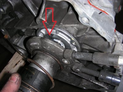
This is where the shim will go.
Here's the sealed and painted tunnel.


Here's the pocket to allow room to plug in the reverse light switch.

A pic of the bell, flywheel and clutch installed.

This was a minor bummer, the alignment tool has the wrong pilot Dia so a sleeve was made to deal with that only to find out Goons clutch came with a selection of different ones (go figure).

Here's a topic (whether or not you need to shim the T.O bearing) of debate and now I know why. The Keisler instructions that came with the TKO I had called for 1/4"-1/2" clearance but my McLeod clutch calls for 1/8"-1/4" (I'll go with McLeod's recommendation).
This is a very quick and easy thing to check especially if you have 2 bell housings laying around (thank you Goon). Start by installing your flywheel, clutch and bell housing then lay a straight edge across the back of the bell and measure the distance to the fingers like in the pic (2 7/8").

Now push the T.O. bearing all the way in bottoming it out and lay a straight edge across the T.O. Measure from the straight edge to the tranny mounting surface like in the pic (2 1/2"). It's important to measure back to the tranny mounting surface on both sides to be sure your holding the straight edge square (measurements should match if holding it straight). Do the math and I've got 3/8" which is great by Keislers instructions but an 1/8" out for McLeods so I'll likely make a 1/4" shim to bring it down to an 1/8".

This is where the shim will go.

HYRDGOON
Well-Known Member
- Local time
- 12:33 AM
- Joined
- Apr 20, 2013
- Messages
- 3,372
- Reaction score
- 2,745
- Location
- Breslau, Ontario, Canada
Tunnel looks awesome and great "How To" on measuring the T.O. bearing clearance.
I'm glad my parts can help lend a hand since I'm not there to!
I'm glad my parts can help lend a hand since I'm not there to!
- Local time
- 12:33 AM
- Joined
- Oct 16, 2014
- Messages
- 27,941
- Reaction score
- 66,030
- Location
- Salisbury, Vermont
Thanks for the great step by step!!
What a work out!!!!! I'll be swore from that night for sure, had a little trouble getting the tranny in and with me being the jack that was holding it forever my arms feel like butter. I put the tranny in the first time pretty easily but couldn't get the last 1/2" to close up so I pulled it out to double check the pilot bearing and clutch disc seating depth (everything was spot on). Not able to find anything wrong I tried again but this time for whatever reason it took forever to get it engaged but once I did it wiggled all the way on without forcing anything. I'm wondering if the pilot bearing had enough grease on it to create a hydraulic effect not allowing the input shaft to push the air out?????? The tranny is DONE, I still need a driveshaft, rear yoke and to install the complete M.C. setup but the tranny is DONE (I hope).
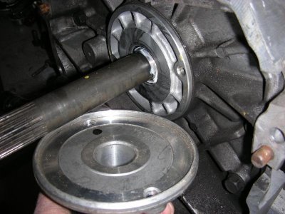
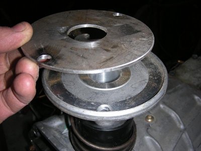
Change of plans on the T.O. spacer, I was going to make a 1/4" thick one to bring it to 1/8" clearance but after looking at the T.O. I changed my mind. In the pic you can see the raised boss on the tranny that centers the T.O. so the input shaft doesn't rub in the bore and then the recess in the T.O. that fits over that, there's the reason for the change. The recess is only .200 deep so by the time you make a .25 spacer and machine the centering bore in the back you'll nearly cut the lip off so I chose to make an 1/8" spacer leaving .075 of the recess to center it and putting me at the .250" maximum limit (by McLeods recommendations).
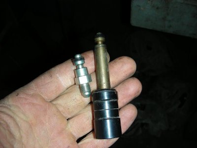
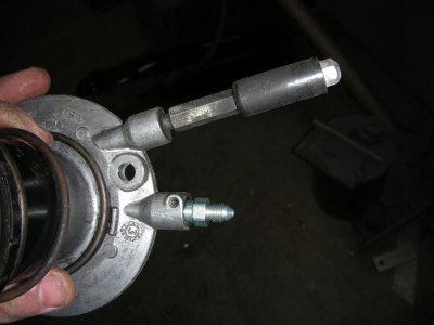
Here's the special fitting from Summit to adapt the T.O. to a 3AN fitting, just drive the roll pin out and swap the fittings. The hose was only about $20.00 from Summit (24" 3AN).
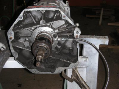
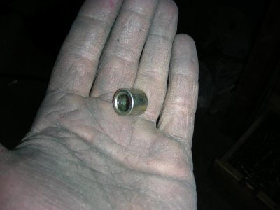
Do not, do not, do not, do not forget to put this in!!!!!!!!!!! I bought a used TKO before this one and had a nasty starter noise and now I know why, this bushing goes in the top starter hole to bush it to a 3/8" bolt and didn't come with the parts for the TKO and of coarse the starter being hidden in the headers I didn't catch it. This was one of my worries was that starter noise so I feel better now knowing why it did it.
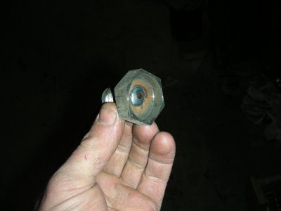
Here's the skip shift solenoid or what's left of it, I just threw it in the lathe, turned the end off and welded the hole shut, now it's just a plug.
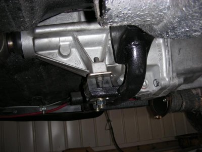
The final product, finished beefing up the tranny mount (can't see the mods in the pic), drilled all the needed mounting holes and got it painted (still need to poke the holes threw the cross member).
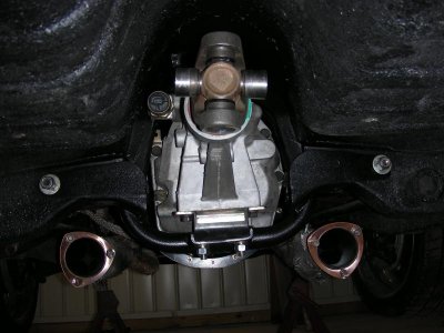
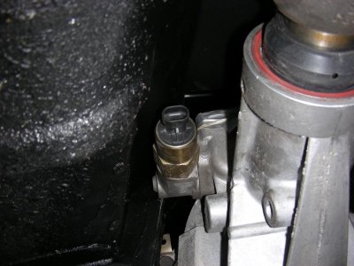
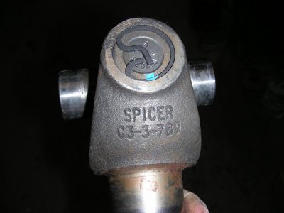
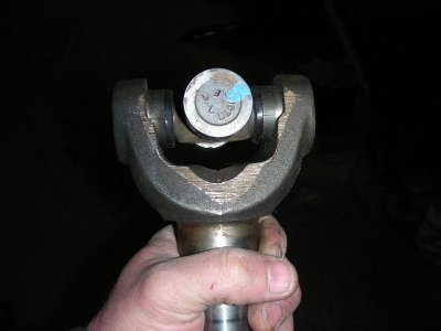
Had some trouble getting the slip yokes but they finally came (they shipped them separate from the tranny's). These things are MASSIVE, I'm definitely beefing up the rear yoke now haha.
- - - Updated - - -
I wanted to add on how happy I am with the quality fit I got with the Quicktime Bell housing, after checking all of the clearances, mounting depths, etc and just the overall quality "These things are nice" . I'll add the part #s and cost for the latest purchases as soon as I find the receipt as well.
Change of plans on the T.O. spacer, I was going to make a 1/4" thick one to bring it to 1/8" clearance but after looking at the T.O. I changed my mind. In the pic you can see the raised boss on the tranny that centers the T.O. so the input shaft doesn't rub in the bore and then the recess in the T.O. that fits over that, there's the reason for the change. The recess is only .200 deep so by the time you make a .25 spacer and machine the centering bore in the back you'll nearly cut the lip off so I chose to make an 1/8" spacer leaving .075 of the recess to center it and putting me at the .250" maximum limit (by McLeods recommendations).


Here's the special fitting from Summit to adapt the T.O. to a 3AN fitting, just drive the roll pin out and swap the fittings. The hose was only about $20.00 from Summit (24" 3AN).


Do not, do not, do not, do not forget to put this in!!!!!!!!!!! I bought a used TKO before this one and had a nasty starter noise and now I know why, this bushing goes in the top starter hole to bush it to a 3/8" bolt and didn't come with the parts for the TKO and of coarse the starter being hidden in the headers I didn't catch it. This was one of my worries was that starter noise so I feel better now knowing why it did it.

Here's the skip shift solenoid or what's left of it, I just threw it in the lathe, turned the end off and welded the hole shut, now it's just a plug.

The final product, finished beefing up the tranny mount (can't see the mods in the pic), drilled all the needed mounting holes and got it painted (still need to poke the holes threw the cross member).


Had some trouble getting the slip yokes but they finally came (they shipped them separate from the tranny's). These things are MASSIVE, I'm definitely beefing up the rear yoke now haha.


- - - Updated - - -
I wanted to add on how happy I am with the quality fit I got with the Quicktime Bell housing, after checking all of the clearances, mounting depths, etc and just the overall quality "These things are nice" . I'll add the part #s and cost for the latest purchases as soon as I find the receipt as well.
Similar threads
- Replies
- 15
- Views
- 2K
- Replies
- 16
- Views
- 2K
- Replies
- 7
- Views
- 543
- Replies
- 5
- Views
- 1K


