• When you click on links to various merchants on this site and make a purchase, this can result in this site earning a commission. Affiliate programs and affiliations include, but are not limited to, the eBay Partner Network.

60 amp alternator wiring

vegiguy

Well-Known Member
Local time
2:51 PM
Joined
Jun 2, 2010
Messages
210
Reaction score
21
Location
Newton, Kansas
This is related to the amp meter elimination post but I decided it needed a separate post on it's own. Mopar had their own way of wiring the 60 amp and up alternators on B-bodies (and other models) that still used the ammeter. Basically it involved running a 6 or 8 gauge wire off of the alternator and splitting it into two 10 gauge wires: one of the 10 gauge legs goes thru a grommet in the firewall to one side of the ammeter, and then from the other side of the ammeter a 10 gauge wire goes back thru the grommet in the firewall thru a 14 gauge fusible link to the starter relay battery terminal. The other 10 gauge leg off of the 8 gauge alternator wire goes thru a 16 gauge fusible link back to a 12 gauge wire and into opening 18 the bulkhead connector to power the main dash splice. The original black and red 12 gauge wires going to the ammeter are cut and the ends taped. The original red wire with the fusible link on it going from the bulkhead connector opening 16 gets removed. Mopar at some point apparently recognized the weakness of their bulkhead connector for running large amounts of power thru it and thought this would take some of the load off of terminals 16 and 18.

I've discussed the upper wiring with an auto electric repairman I trust and he seems to think this is a decent way to wire the system and still keep the ammeter. I brought up the ammeter burning issue and he thought that was caused by loose connections and can be avoided if the connections are kept tight and in good condition. He did admit to doing a lot of repairs to Mopar bulkhead connectors by drilling thru the plastic connector and running the wire straight thru it as in the MAD fix.

I've thought about doing the MAD fix and listened to Mark's spiel about it but I can't bring myself to drilling thru my perfectly good bulkhead connector to do it. Plus I don't like the idea of not being able to service the system with cutting and re-splicing wires in addition to not being original looking which is important to me. My question is: does anyone have a picture of a B-body that was actually wired in the above manor? I'm trying to figure out where the grommet actually was where the main power wires went thru to go to and from the ammeter. If someone could post a picture of this set-up I sure would appreciate it.
 
I don't know that much about wiring but heavier gauge wire to lighter gauge with a fuseible link doesn't sound kosher? I'll be watching to see what others say.
 
You lost me after the 10 gauge wire goes back thru the grommet in the firewall.
dizzy.gif
 
I don't know that much about wiring but heavier gauge wire to lighter gauge with a fuseible link doesn't sound kosher? I'll be watching to see what others say.
No, you're wrong. You need to get down to 12 gauge wiring for the main power circuit eventually because that's what's under the dash at the main dash splice. You need the 16 gauge fusible link to protect the 12 gauge wire. The two 10 gauge wires splits the power from the alternator somewhat into amounts of power more friendly to the parts they have to go thru. The alternative is to re-wire everything in the charging circuit with 6 or 8 gauge wire, which really isn't practical. The problem is people put alternators in their Mopars that are bigger than what the wiring system was designed for; also as electrical components age they lose effectiveness and create more resistance which generates the heat that causes all the problems.
 
You lost me after the 10 gauge wire goes back thru the grommet in the firewall.
dizzy.gif
Another smart-alec: just what this world needs. The alternator wiring layout I described is shown in the 1973 Chrysler service manual (look it up, or if people really want to see the wiring diagram I'll post it when I have time to scan it) so it's not something I just made up to put on a forum. I tried to present information that I thought would be helpful, plus I asked what I thought was a good question. If people don't have anything constructive to offer, such as the picture I asked for, then they shouldn't "contribute" to these forums. It's wrong to use these forums to try to be cute by trying to make others look dumb. Some of us are serious about wanting to restore our cars properly and just need some information.
 
There are several small indentations behind the edge of the power brake booster next to the bulkhead connector: I suspect that's where Chrysler intended holes to be for running extra electrical wires that go thru grommets in the firewall and not the bulkhead connector. I wish someone would chime in that actually has something constructive to off on this.
 
When I did mine, I found an extra hole in the firewall to run the wire through. I bypassed my ammeter.
The extra wiring made the alternator charge better at idle.
 
Another smart-alec: just what this world needs. The alternator wiring layout I described is shown in the 1973 Chrysler service manual (look it up, or if people really want to see the wiring diagram I'll post it when I have time to scan it) so it's not something I just made up to put on a forum. I tried to present information that I thought would be helpful, plus I asked what I thought was a good question. If people don't have anything constructive to offer, such as the picture I asked for, then they shouldn't "contribute" to these forums. It's wrong to use these forums to try to be cute by trying to make others look dumb. Some of us are serious about wanting to restore our cars properly and just need some information.

You take life too seriously.
You are both right and wrong.
Yes, bad connections and worn out devices will draw more amps due to increased resistance and result in multiple electrical issues. The worst of which is a fire.
However, your earlier statement about an alternator being too big is not exactly valid. Amps are a measurement of consumption, not pressure. A cars electrical system will consume only what is needed. If everything is in proper working order, you could put a 1000 amp regulated alternator on a car. Saying an alternator is too big for a car is like saying the battery has too many CCA's.
 
This is related to the amp meter elimination post but I decided it needed a separate post on it's own. Mopar had their own way of wiring the 60 amp and up alternators on B-bodies (and other models) that still used the ammeter. Basically it involved running a 6 or 8 gauge wire off of the alternator and splitting it into two 10 gauge wires: one of the 10 gauge legs goes thru a grommet in the firewall to one side of the ammeter, and then from the other side of the ammeter a 10 gauge wire goes back thru the grommet in the firewall thru a 14 gauge fusible link to the starter relay battery terminal. The other 10 gauge leg off of the 8 gauge alternator wire goes thru a 16 gauge fusible link back to a 12 gauge wire and into opening 18 the bulkhead connector to power the main dash splice. The original black and red 12 gauge wires going to the ammeter are cut and the ends taped. The original red wire with the fusible link on it going from the bulkhead connector opening 16 gets removed. Mopar at some point apparently recognized the weakness of their bulkhead connector for running large amounts of power thru it and thought this would take some of the load off of terminals 16 and 18.

I've discussed the upper wiring with an auto electric repairman I trust and he seems to think this is a decent way to wire the system and still keep the ammeter. I brought up the ammeter burning issue and he thought that was caused by loose connections and can be avoided if the connections are kept tight and in good condition. He did admit to doing a lot of repairs to Mopar bulkhead connectors by drilling thru the plastic connector and running the wire straight thru it as in the MAD fix.

I've thought about doing the MAD fix and listened to Mark's spiel about it but I can't bring myself to drilling thru my perfectly good bulkhead connector to do it. Plus I don't like the idea of not being able to service the system with cutting and re-splicing wires in addition to not being original looking which is important to me. My question is: does anyone have a picture of a B-body that was actually wired in the above manor? I'm trying to figure out where the grommet actually was where the main power wires went thru to go to and from the ammeter. If someone could post a picture of this set-up I sure would appreciate it.

It would be great to know just exactly what year,make and model you're referring to as all cars were wired somewhat differently. I gather by your explanation that your fuse panel is under the dash, and if so, all power went through the amp meter first and then to the various sub circuits via the fuse panel so it could actually read the load correctly. It is true that most issues occurred at the bulkhead connector and seldom at the amp meter itself unless the attaching nuts on the studs came loose. Perhaps all you need do is remove the terminals from the bulkhead connector and inspect/clean/replace them as necessary. Using a small pair of needle nose, squeeze the male spade terminal (broadside) on the firewall side and pull it out through the back of the housing by the wire. Then you can asses it's condition. New ones are available.
The female side is removed using a very small screwdriver inserted from the wire side and depressing the little retaining finger on the frontside of the connector and pulling the wire out the rear. Cleaned thoroughly or replaced and lubed with dielectric grease will prevent future corrosion. The car ran for many years after manufacture and can run reliably for many more if you prevent the arcing that takes place at these terminals causing a meltdown.
 
You take life too seriously.
You are both right and wrong.
Yes, bad connections and worn out devices will draw more amps due to increased resistance and result in multiple electrical issues. The worst of which is a fire.
However, your earlier statement about an alternator being too big is not exactly valid. Amps are a measurement of consumption, not pressure. A cars electrical system will consume only what is needed. If everything is in proper working order, you could put a 1000 amp regulated alternator on a car. Saying an alternator is too big for a car is like saying the battery has too many CCA's.
What you said is what I basically said. People put too big of alternators FOR THE WIRING OF THEIR CARS
 
Sorry, hit the wrong button. Basically calling me wrong about what I said about people putting too big of alternators for their wiring and that causing problems is calling yourself wrong, too, which IS wrong since we were both right.

I'm going to sign off from this thread because it's clear no one is serious about helping me with what I brought up in my original post and the thread is taking a negative turn.
 
The car pulls from the alternator. Unless the voltage regulator is bad, the car will never see the full output of a larger alternator unless the car demands that much power.
 
Going to your original point.... You will have to cut and splice wires if your car IS NOT set up the same as the diagram you are looking at.
There are plenty of open areas on the firewall to drill a hole and use a grommet to run the new wire.
Hope that helps a little.
 
Another smart-alec: just what this world needs. The alternator wiring layout I described is shown in the 1973 Chrysler service manual (look it up, or if people really want to see the wiring diagram I'll post it when I have time to scan it) so it's not something I just made up to put on a forum. I tried to present information that I thought would be helpful, plus I asked what I thought was a good question. If people don't have anything constructive to offer, such as the picture I asked for, then they shouldn't "contribute" to these forums. It's wrong to use these forums to try to be cute by trying to make others look dumb. Some of us are serious about wanting to restore our cars properly and just need some information.
You need to drop the attitude. I was not being a "smart-alec", nor was I trying to make anyone "look dumb". Quite the opposite, as I was trying to say that it was I who did not understand it. Relax and read my posts a bit closer next time before you start name calling.
 
Last edited:
Ok! Let's see.

What MaMopar did is just replace the 12 gauge alt and batt wires on engine harness ( and lighting on 3rd gens ) for 10 or 8 gauge wires, and not run it through the weak packard terminals at bulkhead with I guess more strong bullet kind terminals on engine bay and from there up to ammeter through the firewall with a grommet, with same gauge wires.

They didn't cut or remove any wire from the underdash harness. Original 12 gauges wires up to main splice was kept there. The wire between splice and amm remain the same, just feeded from the thicker wire at amm.
 
I think 12 gauge red and black wires up to bulkhead on can side were also kept in place, just not running on engine bay side

I'm on the road so can't post more info or diagrams right now
 
Last edited:
You take life too seriously.
You are both right and wrong.
Yes, bad connections and worn out devices will draw more amps due to increased resistance and result in multiple electrical issues. The worst of which is a fire.
However, your earlier statement about an alternator being too big is not exactly valid. Amps are a measurement of consumption, not pressure. A cars electrical system will consume only what is needed. If everything is in proper working order, you could put a 1000 amp regulated alternator on a car. Saying an alternator is too big for a car is like saying the battery has too many CCA's.

The car pulls from the alternator. Unless the voltage regulator is bad, the car will never see the full output of a larger alternator unless the car demands that much power.


FINALLY I CAN READ COMMON SENSE ON THIS!

Another example is when you plug your cellphone charger into the same wall outlet than a hair dryer! Or your dishwasher!

If your car needs 40 amps to work, no matter where it comes, alt ot batt, the car will suck that! The deal is left out of the play as much as posible the batt. This will save the ammeter too. Keep all the play of the power on alt side of the ammeter. How to do this? An alt able to provide all the juice the car will demand at the lower RPMs as posible, so at IDLE. No matter if is rated 80, 150... 1000 amps, but able to source everything at iddle. The car won't pull out more than it needs. Alt doesn't push the amperage.


Theeeen next step is mantenience and reinforce the wiring SPECIALLY on that side.
AND NEVER SOURCE ANYTHING from batt post. This will be read by the amm like a discharge process so an unnecesary stress added on the amm and wiring between amm and batt
 
Last edited:
Need to note... when the alt is not able to feed the amperage the car demands, then the Voltage will begin to drop, but thats because the system is limited by the regulator to not feed more Voltage

everybody compares electricity to water, BUT I preffer to compare it with something easier to feel it by ourself in our own body. Maybe that will be easier to understand.

try to imagine 5 guys pushing a car on a flat street. everyone will make some force on it, but suddenly find a hill. The force every guy will apply will need to be increased OR get couple of guy more to push everyone the same ( including the new two guys )

Voltage is the number of guys
Amperage is the force everyone applies.

The car is demanding more force to be moved on to go up the hill. Every guy was able to push more on the flat surface of the street but the car didn't need more so the guys didn't push harder untill was required when they found the hill


THIS WILL BE JUST AN EXCEPTION IF THE GUYS ARE JEDIS!!!
 
I'm using a 100 Amp modern alternator in my 67 Charger, all going thru the original ammeter.

The ammeter is very good to have, I know if current is going in or out. The wiring is beefed up alternator-ammeter-battery, and straight thru the bulkhead connector.
Important with stiff wires is to not have them bending on the screw terminals in the ammeter, and of course no loose connections.

The amount of current is no problem, the original ammeter can handle more current than the alternator will output.

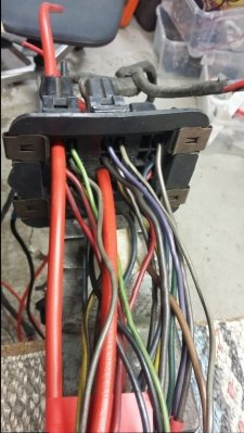
Attaching a picture showing my bulkhead connector. I've since used Howies hockey tape to make the wires look original, and also tested that the hockey tape doesn't burn.
It all works nicely.

20160126_092701.jpg
 
One reason I like to compare water to electricity is it helps some understand it when teaching to anyone learning about electricity. Its like if you take a point ign in a Mopar and turn the key on with the points closed then current flows and you have 12 volts at the battery pushing it. But you have a ballast resister in the circuit so when you check the volts at the coil + terminal you get about 7 volts. Now open the points and no current flows and you get 12 volts at the coil. Many just dont understand it so I like to compare it to water in a garden hose. Say you have water flowing in a hose and it has 12 psi pushing it. Now you put a restriction in the hose and then read the psi after the restriction and it reads 7 psi. Now go after where you read the psi and close a valve to stop the water from flowing and now it reads 12 psi. Even with the restriction in the hose it will still read 12 psi after the restriction with the water flow stopped after the restriction because it will built up to the pushing psi with no flow. Kinda the same reason you see 12 volts at the coil + terminal with the points open and no current flow instead of 7 volts it reads after going through the ballast with current flowing.
I had a tech who had a problem with an electric fuel pump not working much. He unplugged the pump connector and got 12 volts so he replaced the pump and it still would barely work. So he asked me to look at it for him. I told him to check the voltage at the pump and he said he did but I told him to backprope the connector and leave it hooked up like a voltage drop test and then he only got 3 volts. So I told him he had a bad connection before the pump or burnt contacts in the relay and it turned out to be a cut wire in the car hanging by a few strands. Even after I told him why it read that he could not understand it. And this was a 20 year tech. Ron
 
Auto Transport Service
Back
Top