• When you click on links to various merchants on this site and make a purchase, this can result in this site earning a commission. Affiliate programs and affiliations include, but are not limited to, the eBay Partner Network.

'64 Fury Pro-Touring

Thanks Prop!
We're in the midst of moving both our company and home to Las Vegas so progress has pretty much been halted at this point, but before things came to a halt I got some of the underside of the cowl finished off as well as deleted the cowl vents themselves. Once the move is all complete and I'm back at it I'll get some shots and update the blog more extensively, but in the meantime I've got boxes to pack!

Talk to you all soon
 
Vegas...Wow! Good luck with the move Bob. Hope all goes well. Look forward to your progress once the dust settles.
 
Holy crap, it's been over two years since I've updated the blog, and while I wish I could say I've been working diligently on the Fury all that time that'd be a lie. After moving to Vegas it took me over a year to get my shop together (over $6K in electrical) and in the interim business has sucked so I haven't been spending time/money on the car, rather trying to keep the doors open. Regardless, I have been making some progress so I'll begin putting up some new progress shots.

Once I finally got back to work I realized I've got lots to do, including a trans cross-member, exhaust, and full rear suspension layout, not to mention the firewall and floors, and it appears the logical step would be to get the trans mount and the rear suspension finished off, then move to the exhaust, then on to the firewall, then to the floors, so here's where I'm at:

Exhaust_through_chassis01.jpg

I've had the engine, trans, and headers in before but needed to mock them up once again so I could build the trans cross-member, especially since the exhaust will pass directly through the cross-member like it does on a C3 Vette. You'll notice I have the factory 833 trans in place. Well, life does tend to get in the way and I don't feel like dropping $2500 on a Tremec at the moment so in with the 4-speed, though hopefully I'll be able to change over or add a Gear-Vendors as some point.

Exhaust_through_chassis02.jpg

The 3" stainless exhaust is being routed directly through the frame rails because there's just no way to run exhaust tubing around the truck arms. I picked up some flexible stainless unions that will be welded between the header flange and the frame pass-through; I figure it'll dampen the vibration and noise quite a bit.

Borla In Place.jpg

These tiny stainless Borla's fit in a cavity between the Art Morrison chassis and the original surface of the factory rocker panel. Originally I'd planned on cutting the rocker panels to fit turnouts but have since decided to take the easier route and simply put turndowns on the ends of the mufflers. This will also help quell the noise a bit, though admittedly that isn't really a factor.

Rear_with_Watts01.jpg

Here's a straight on view of the Watts link Jimmy fabbed up for me; I wish I had 1/10th the fabricating skill he does! I have to have another adjustable rod made up; we were waiting until we knew the placement and could measure the length. One thing to note: I don't believe the 9" housing will be strong enough to hold the pressure exerted by the Watts pivot, so all the nice powder-coating will go to waste because I'm going to add some gusseting.

Rear_TruckArsm_Watts.jpg

Here's the same view from a bit different angle; it gives a really good view of just how long the truck-arms are and why I couldn't run the exhaust out the rear.

Below are a couple side views of the suspension, including the single adjustable Vari-Shock coil-overs. You can also see a bit of the floater hubs and the lowering blocks, though I don't know if I'm going to use two sets (as shown) or just one.


Rear_TruckArms_Watts_Side.jpg

RearTruckArms_Watts_Side_Closeup.jpg

- - - Updated - - -

One thing I forgot to mention; if you look around the inside perimeter of the chassis plate you'll see I've mounted LED's for added light. What an AMAZING difference they make while working on the car! There are two 16' lines, one on the left, one one the right, and are controlled be a dimmer and 12V power supply.
Got it all on eBay for under $40!.
If you want specifics on what I used let me know.

- - - Updated - - -

Please note: if you look closely at the Watts Link mounts you'll notice I installed them incorrectly, I initially had it bolted to the truck-arm, which would not have done anything. I updated it and will have pictures of the corrected locations in following posts.

Exhaust_through_chassis01.jpg Exhaust_through_chassis02.jpg Borla In Place.jpg Rear_with_Watts01.jpg Rear_TruckArsm_Watts.jpg Rear_TruckArms_Watts_Side.jpg RearTruckArms_Watts_Side_Closeup.jpg
 
WOW looking real good thanks for sharing and updating also :icon_thumleft:
 
great update photos. Hope everything else is working out for you.
 
Wow, between you and Superfreak I'm really wanting my next build to be ridiculous like yours "looks like a lot of fun". I'll be keeping an eye on this build. I really like the exhaust idea you have "should really look good". I may have missed something but what's your coilovers mounted to? looks like maybe the factory shock mount, I think I'd go with something more significant if ride weight will be resting on it (sorry if I missed something). I was reading your thread and saw the talk about the vertical welds, if welding up hill the trick is to pause on the sides and move quickly across the center "everyone's got they're way but that's the way it's taught for pipe welding". I personally like welding down hill with the MIG. Now I've got to ask "what's up with the Avatar" 666, maybe I missed it?
 
Hey fellas,

Thanks for the kind words and encouragement; this hole keeps getting deeper no matter how hard I try and fill it! I've gotten farther than these updates show (I'll get more up soon) but no matter where I turn something new jumps up, but at least it keeps me out of the bars!

747 - thanks for the welding tip, I'll certainly give it a try. As for the avatar, my wife has called me "Satan" for years so I roll with it. My Caddy license plate is "666 CTS V" and the Fury will be "666 Fury".
 
Car is looking trick, love all the cool fab work... I know about bottomless pits & endless projects too... I've been building them for 35 years now...LOL... keep up all the great work
 
Based on other members observations and input, I pulled my head out of my butt and got the Watts link straightened out. Thanks again for the heads up!
The mounts are not completely welded in but they're certainly not going anywhere.
Next is going to be work on the exhaust then back to the rear shock mounts: the factory location I'm currently using might not have enough clearance but I won't know until I get some other parts and start moving things up and down.
I'm having all kinds of difficulty with the welding even after changing over to a Lincoln 200 MIG (plenty of power!!!)
For instance:
1) I'm seeing great penetration in the base metal but I'm getting far too much weld material on the weld itself. I've tried slowing down the wire speed but then I don't seem to get the consistent penetration
2) I grind everything I'm going to weld so there's no contaminants, yet I'm getting a great deal of popping and sputtering; I've got the gas pressure at a touch over 30 and am considering going a bit higher but don't want to be pissing gas pointlessly
I'm curious if the replaceable tip is too far inside the cup, leaving too much distance between the tip and the material being welded? I've watched some instructional vids and know how critical this distance is.

Watts Link - Completed.jpg

- - - Updated - - -

I have GOT to start playing that Power-Ball because all this work and real-life stuff keeps getting in the way of my working on the Fury! Over the past few weeks I've had precious little time to devote to the car but I was able to notch the rear frame rails and then spent my entire Father's Day weekend working on the Fury and finished off one of the most crucial elements; the transmission cross-member. Now that the cross-member is finished we can finalize the exhaust routing, then drop in a floor, build the trans tunnel (that'll come much later) and build the firewall. Oh yeah, my ability to weld seems to have miraculously returned now that I re-did the ground strap! Not that I'm some kind of artisan or anything but my welds are MUCH better than before! Here are some pix and updates:

While the 9" rear axle tubes didn't actual contact the frame rails, they were way too close for my comfort so I notched the rails 1". I simply cut vertically on the front and rear of the rail then joined the cuts with a horizontal cut, removed 1" from the top of the piece I just removed, then welded it back into the frame rail. I filled the gaps with 1/8" plate to ensure the strength, and while the rail lacks the perfectly rounded appearance of the original I can live with the results:

Frame Notch.jpg

After finishing off the frame rail notches I got to work on the cross-member, which is very similar in concept to the cross-member of my '70 Vette; the exhaust tubing passes directly through the cross-member as opposed to bending or contouring the cross-member around the exhaust. Here is how I did it:

Exhaust Passthrough Mockup.jpg

Exhaust Passtrhough & Extension.jpg

CrossMember Mockup II.jpg

Crossmember Mockup.jpg

CrossMember In Place.jpg

Finally A Bead.jpg

I don't have a TIG welder nor the talent to use one, so before anything else happens I need to take my stainless exhaust pieces and have some flanges TIGged in place, then we'll finalize the exhaust and move on to the other areas I mentioned above. It'll probably be a couple weeks minimum before I can do much more work; family and work call me again!

- - - Updated - - -

Moving to a new area means building new relationships and finding quality craftsman, and luckily I've found a guy who knows how to wield a TIG torch; his name is Adam and he's co-owner of a prop-repair shop in Henderson. Over the past week Adam welded on the stainless flanges and flex-joints of the 3" exhaust which if all goes well I'll be getting mocked into place this weekend.

Exhaust.jpg

DriveExhaust.jpg

PassExhaust.jpg

- - - Updated - - -

Passing the exhaust through the frame-rail seemed like a good solution to a problem I caused myself (running Truck-arm rear suspension) but damn it's been a ton of work to make functional, including the exhaust.

Since the exhaust passes through the frame rails at 45 degree angles and the tubing itself has bends and flanges attached, sliding the tubing through the rails became a frustrating repetition of making the holes larger and larger until I could snake the tubing through, and in the end all that cutting left me with oblong holes in the frame that were MUCH larger than the 3" exhaust passing through. Knowing the exhaust tubing (stainless) would be an integral part of the frame (for strength) meant I couldn't have huge gaps around the tubing so I spent literally hour after hour fabricating little crescent shaped patches out of extra frame rail material. Each crescent was unique so making a single pattern was useless, hence each one of the 4 was rough cut out with the Plasma cutter then meticulously ground and filed to fit. Below are some shots of the crescents and the overall exhaust layout:

These two shots are the crescent patches (outside of frame rails) tacked in place. I am going to use a different method to patch the holes on the inside of the frame rails and want to wait until I have those patches done before final welding everything.

Left Pass-through.jpg

Right Pass-through.jpg

Exhaust Layout.jpg

Cross-Member & Pass-throughs.jpg

I can't even remember when I bought the stainless Borla mufflers but having seen bunch of Sprint cars running Spintech mufflers I thought they'd be worth a look. Why? The Borla's are 4 1/2" thick, which was as thin a muffler as I could find with 3" inlet/outlets, and even at only 4 1/2" the thickness will force the muffler to hang slightly below the bottom of the frame rail and protrude slightly into the floor pan. The Spintech 6000 series turn out to be only 4" thick so you know I had to go ahead and order those, right? Yep, so anyone looking for a brand new set of polished stainless Borla mufflers let me know :)

Here's what Spintech's look like:

Spintech 6000.jpg

- - - Updated - - -

My free time to work on the Fury has been a bit limited lately but I have been making some solid progress. Without having a mill or lather at your disposal sure slows things down, but with some patience and sweat I finally finished the frame reinforcements that surround the exhaust tubing. Where the reinforcements meet the frame I've used standard MIG welding but for welding the reinforcements to the stainless exhaust I'll need to pick up some "Tri-Gas" and stainless wire; I figure to do that this week if time permits.

Here are a few shots of the progress I've made over the past couple weekends, and one thing I'm really happy about is the fact the new Spintech mufflers are slim enough they do not hang below the level of the frame. Granted, the turn-downs do but I can live with that so long as the mufflers don't.

Gussets around exhaust - Driver.jpg

Gussets around exhaust - Driver2.jpg

Gussets around exhaust - Pass.jpg

Gussets around exhaust - Passenger2.jpg

Spintech mounted - Driver.jpg

Spintech mounted - Passenter.jpg

Spintech outlet - Driver.jpg

Spintech outlet - Passenter.jpg

- - - Updated - - -

Progress has been slow but steady over the past few weeks and either I'm punch-drunk or there really is some light at the end of the tunnel! If you've read through the entire post you saw the floors had already been mocked up but dealing with the driveshaft/trans tunnel was a completely separate process, so that's what I've been focusing on lately.

To get the tunnel started I put the rear suspension back in the car, and using a measured drawing located the centerline of the pinion (I don't have a carrier yet) and shot a line from the centerpoint up to the trans yoke. Knowing where the shaft would run was the easy part but I had to remember the parking brake will be fitted to the pinion as well so I needed to ensure there was enough room, both horizontally and vertically, for the caliper and rotor to fit. Once I had the measurements dialed in I cut the far rear of the floorpan in an arc and welded a flange around the perimeter.

attachment.jpg


attachment.jpg


attachment.jpg


attachment.jpg

I have the tunnel completed and ready to go in, but like a dunce I forgot to take a picture. I'll snap one soon and show you the finished look. I'm waiting on new arms for my spot-welder, and as soon as they arrive I'm going to start putting the floors in permanently...I can't wait!

- - - Updated - - -

I swear it feels like everything in the world is conspiring to keep me from working on the Fury! $5K worth of electrical to build my shop, two broken arms last Christmas, surgery 3 weeks ago to repair damage when I broke my wrist, when does it end? Enough pissing and moaning, I've FINALLY begun putting the floor pans permanently in the car! I can't wait to get this done but for now I'm just about halfway so here are some pix:

I chose to put a rosette weld about every 2 inches or so, which combined with the heavier gauge steel I used makes for one sturdy floor! Glad I'm using fiberglass for all the body panels because with the AM chassis and all the steel I'm using I'll need to cut some weight!

One thing I have consistently seen; "Weld-through Primer" makes for one messy, splatter-filled weld! It's been so long since we did the wheel tubs I'd forgotten how terrible that primer is to weld through, but did I ever get a shocking reminder! Granted, it's better than not priming the surfaces at all but it does make for some icky welds and lots of clogging the tip of the gun.

Oh well, lunch is done so now it's on to the driver side.

attachment.jpg


attachment.jpg


attachment.jpg

- - - Updated - - -

Holy sh*#, it's been 6 years since I began this build, which says I'm either REALLY slow or REALLY persistent; I hope it's persistent! I mention this because I reached a milestone today, the floor of the Fury is actually in! I can't believe it but yep, it's in and secure. Next I'll get the back half of the tunnel in then get moving on the firewall and cowl, but for now I'm going to savor the moment. Here are some shots:

attachment.jpg


attachment.jpg


attachment.jpg


attachment.jpg

- - - Updated - - -

Not a lot of time to work today but I got the rear half of the tunnel welded into place.

I don't know if I EVER remember having so much weld splatter as what I experienced putting in the floors and tunnel. No matter how much I ground and wire-brushed the surfaces it's as if the weld would pop/splatter/explode and leave a divot in the puddle, all of which was surrounded by a black soot. More power, less power, more wire speed, less wire speed, nothing seemed to change the phenomenon. I have to figure this out so any ideas would be most welcome.

Here's the tunnel:

attachment.jpg


attachment.jpg

- - - Updated - - -

Today marked a milestone of sorts; the floor and tunnel are now complete all the way up to the firewall! Who'd have thought a trans tunnel would be so much work, but with all the various angles, elevation changes, etc, this thing was WAY more difficult than I ever would have imagined. I guess I could have used thinner steel than the 16 gauge I've been using throughout the build, but I like the strength and solidity it adds.

Here are a couple shots of the tunnel in place, and you can see how difficult it was to meld the factory tunnel/hump into the finished tunnel. BTW - sorry about the blurry shots, I guess I'm neither a welder OR a photographer!

attachment.jpg


attachment.jpg


attachment.jpg

One thing I did find out via some experimentation before installing the front half of the tunnel today; I slowed down the feed speed on the welder well below the recommended setting and found my weld penetration to be better as well as less popping and f'ing up. Still not perfect but certainly better, so maybe I'll switch to .030 instead of the .035 I've been using. Just a thought.

- - - Updated - - -

I've now tried .023 at settings and wire speeds from high to low, with every combination in between; no real luck.
I've gone back to .030 while trying every combination I can think of; no real luck.
I've raised and lowered the gas flow rate; no real luck.
The welding results come out to a far lower standard than I have been able to produce in the past, so now I'm left to wonder if:
a) I've got some kind of degenerative disease that's eroded my skills and left me unable to figure out simple problems
b) the bottle of gas I've been using (almost empty) may have an incorrect mixture
c) go back to "a"

Is there anyone with welding skills located in Las Vegas that'd be willing to come to my shop and try to diagnose WTF is wrong? I could really use the help!

- - - Updated - - -

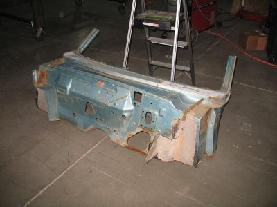
The original cowl turned out to be just too far gone; I couldn't see continually fighting with it to make it work, so I got hold of DVAS and purchased a complete cowl/firewall. Granted, when the part arrived it turned out to be from a '65 as opposed to a '64 but save for some small/minor differences the replacement is identical to the original, and since this is anything but a concourse restoration I'm completely devoid of any concern.

Here's the replacement piece. If you're a real Mopar fiend you'll notice the shape of the hole for the steering column and some differences around the heater/airbox area, but the overall shape of the window frame, door frame, cowl, etc. are all the exactly the same.

attachment.jpg

Before I cut the original sheet metal away I made some alignment jigs that mount to the chassis plate; they're removable but are self-aligning so I can take them off and put them on with ease and they're always in the same exact location. In the second picture you'll see a vertical 1" x 1" bar, the upper edge lining up with the factory seam where the door jam meets the A-pillar; what a perfect point this turned out to be in terms of lining up the replacement!

attachment.jpg


attachment.jpg

I also added some vertical, horizontal, and diagonal bracing to the cowl area inside the car, using mounting locations provided by the factory, that way I could make the replacement cowl line up accurately to the same position as the original:

attachment.jpg


attachment.jpg


attachment.jpg


attachment.jpg


attachment.jpg
 

Attachments

  • Replacement Cowl.jpg
    Replacement Cowl.jpg
    53.1 KB · Views: 528
The last few weeks have left precious little time to work on the Fury, but when I've had a chance to get out in the shop I've been lining up the replacement cowl and locking it in place. Not an easy job but the jigs I made really worked out well, so over the last couple of days I've begun the welding process. While not finished by any means, the cowl is now permanently joined to the rest of the car and the roof is supported by the A-pillars as opposed to the bracing. It's time for a new bottle of gas for the welder and hope springs eternal the new bottle will improve my welding efforts.

Here are some shots of the replacement cowl in place:

Cowl_Replaced01.jpg

Cowl_Replaced02.jpg

Cowl_Replaced03.jpg

CowlReplaced04.jpg

CowlReplaced05.jpg

Cowl_Replaced01.jpg Cowl_Replaced02.jpg Cowl_Replaced03.jpg CowlReplaced04.jpg CowlReplaced05.jpg
 
Those last welds you posted didn't look as if anything was wrong with the welder but that you just need to get your settings right "more heat less wire speed". One of the things that will cause you grief is clogging, it can be in the tip, cable or just after the feed rolls. I cut the wire and push it in and out by hand to make sure it moves freely, you can buy wipers to put on the wire before the rolls to wipe all of the dirt off and keep this from happening but it will cause all kinds of spit and spattering do to the wire stopping and then jumping out. Another is the type of gas, what are you running? most run 75 25 or 80 20 mix. I use .035 and .032 with no issues. 30 psi is just wasting gas, you shouldn't need more than 12 maybe 15 for a good weld. Try setting your wire speed by ear, I'll hold the gun to a piece of metal and hold the trigger while adjusting the speed until it gets that nice smooth frying eggs sound. On the weld threw primer, I'm with you "it sucks" but what worked for me was to run a drill bit down into the hole to be spot welded and remove it from the weld area "really helped". Good luck with a very ambitious project.
 
Great to hear you're up on your feet out there in Vegas carnalsupply. Trying to balance a move, a job and a major car projects has to be quite overwhelming. As always, progress is looking great. Nice to see the Fury getting some love. Keep up the good work.
 
That is some crazy workmanship on that exhaust. I think once you get everything primed and painted on the rear frame rails, nobody is going to tell the difference.
 
Those last welds you posted didn't look as if anything was wrong with the welder but that you just need to get your settings right "more heat less wire speed". One of the things that will cause you grief is clogging, it can be in the tip, cable or just after the feed rolls. I cut the wire and push it in and out by hand to make sure it moves freely, you can buy wipers to put on the wire before the rolls to wipe all of the dirt off and keep this from happening but it will cause all kinds of spit and spattering do to the wire stopping and then jumping out. Another is the type of gas, what are you running? most run 75 25 or 80 20 mix. I use .035 and .032 with no issues. 30 psi is just wasting gas, you shouldn't need more than 12 maybe 15 for a good weld. Try setting your wire speed by ear, I'll hold the gun to a piece of metal and hold the trigger while adjusting the speed until it gets that nice smooth frying eggs sound. On the weld threw primer, I'm with you "it sucks" but what worked for me was to run a drill bit down into the hole to be spot welded and remove it from the weld area "really helped". Good luck with a very ambitious project.

Hey 747,
When I decrease the feed speed at higher settings the wire literally just explodes on contact, either disintegrating itself or sometimes blowing a hole, but I'll keep at it, adjusting up and down.
Clogging isn't nearly as prevelant as when I'm trying to go through the weld-through primer, but I keep the nozzle gel'd up now to help avoid the problem anyway.
I just finished the bottle I have so when I go to the supply house I'm going to ask for their recommendation on gas mixture, describing exactly what I'm up to; hopefully the mixture is/was part of my problem.

Thanks much

- - - Updated - - -

Hey there Propwash & RR'man, thanks for the encouragement and kind words, they're much appreciated. I guess if things were always easy there'd be less to appreciate, so I consider myself pretty lucky overall.

Take care
 
"Wow" explodes on contact, I'd really go through everything and track it down "sounds like something isn't right at all". A couple other things to check is whether or not you have the pos and neg leads correct and make sure your using the correct tip for the wire. I don't use the nozzle dip "seams to mess with the welds". Hopefully you find someone down there to help you out, it's probably something simple. Just keep after it.
 
Hey everybody, I really appreciate the help and advice you've been giving about the welding, so here's where I am:

1) Picked up a new bottle of gas (25/75) - last bottle was both old (3+ years and near empty)
2) Checked every orifice and passage I could find on the welder for blockages, crud build-up, or anything that could impede the flow of wire or gas - found none
3) Checked for leaks in the gas line from the regulator to the gun - found none
4) Changed out the ground connector at the welder itself just to ensure it has a solid connection (already changed out the connection at the clamp)
5) Checked the polarity against the factory manual - negative is connected to the ground and positive to the gun, just as the manual prescribes
5a) I actually switched the two and tried to weld and it was quickly obvious the polarity needs to be as the manual directs; there was NO welding going on, just spattering and crap buildup
6) Re-checked the settings of the welder against the chart inside the welder itself (recommended settings for 16 gauge and a 25/75 mix are B/110)
7) I began taking pictures and video, as requested, in an effort to illustrate what the results are looking like
7a) I obviously know how to upload pictures but video is something new for me, so if the video doesn't link up as it should I'll figure something else out because they clearly illustrate the problem(s) I'm having, and I think they do so far better than the still shots, but regardless, here goes (this may take a couple replies to get it all in):

Sorry about the blurry picture but you can still make out the fact I have plenty of gas pressure in the bottle and my line is seeing 20+cfh of gas
IMG_1996.jpg

The polarity is correct with the positive lead going to the gun and the negative to the clamp
IMG_1997.jpg

No obstructions at the gun tip; the gel is a waxy like substance that definitely helps keep crap from sticking. BTW - I'm using .030 wire and the tips are also .030 (checked them as well)
IMG_2003.jpg

There's a panel on the rear of the welder that also has various possible settings, so I checked them against the manual and they appear to be correct as well, though I am unsure why my machine has multiple wires as opposed to the simplified illustration shown in the manual
IMG_2006.jpg

Lincoln PowerMIG 200 Manual 11.jpg

Now for actual weld pictures (next reply)

IMG_1996.jpg IMG_1997.jpg IMG_2003.jpg IMG_2006.jpg Lincoln PowerMIG 200 Manual 11.jpg
 
love this build :headbang: how old is the wire some times if its corroded it do that
 
Here are the welder settings and the welds themselves:

The Lincoln chart calls for B/130 when using a 25/75 mix on 16 gauge, so that's what I'm set at:
IMG_1999.jpg

IMG_2002.jpg

These are a number of practice beads I made on an area of the original and replacement cowl, where I've basically reversed the order of the pieces I used on the car itself. I figured it would be a good idea to practice on the same exact material I'd be working on for real, and do so with the metal in the vertical plane (which makes the problems worse). FUGLY!!!
PracticeBeads.jpg

These practice beads were all done with the material (unused 16 gauge sheet, ground clean) in the horizontal position, and while they're an improvement over the vertically mounted material above they are far from attractive. There are a number of different heat and feed settings used throughout but of particular interest is the comparison between the lower left corner with a setting of B/130 (as recommended) and the upper right with a setting of D/190-200
PracticeBeads2.jpg

After cranking up the heat to setting D and increasing the wire speed enough to begin hearing a bit of the welding "sizzle" I'm supposed to, I tried welding with the sample material in the vertical plane, and while not a thing of beauty they are certainly better than what I'd been seeing on the old cowl.
PracticeBeads3.jpg

I tried the same setting (as in the last picture) on the old cowl section shown in the 3rd/middle picture above and the results SUCKED once again; it's as if the DP-40 primer, the age of the metal, the acid the car was dipped in, or any combination of those elements are combining to screw me.

My next reply will hopefully have a couple of short videos that much more clearly give an idea of what I'm dealing with (or screwing up).

- - - Updated - - -

I've never uploaded video before so hopefully this works:


This is probably the best bead I've been able to lay down, but the settings are SO high by comparison to what Lincoln recommends, meaning I'm on the verge of blow-through at every moment (clearly evident in my previous reply where you'll see some massive blow-through).
Of particular note, watch/listen to the first 12 seconds, where you'll hear the wire literally just banging against the metal as opposed to beginning the weld. After that point the weld actually begins to happen but throughout you'll hear the weld popping and "back-firing", literally stopping the weld in its tracks then picking up again.
[video=youtube_share;p3s7aRyxzjM]http://youtu.be/p3s7aRyxzjM[/video]​

My next reply will show what happens when I try to use the settings recommended by Lincoln.

IMG_1999.jpg IMG_2002.jpg PracticeBeads.jpg PracticeBeads2.jpg PracticeBeads3.jpg
 
That tip looks way to far inside of that nozzle, mine is only about an 1/8"-1/4" behind the nozzle.
 
Auto Transport Service
Back
Top