• When you click on links to various merchants on this site and make a purchase, this can result in this site earning a commission. Affiliate programs and affiliations include, but are not limited to, the eBay Partner Network.

Battery Not Charging

67SniperHockey

Well-Known Member
Local time
9:38 AM
Joined
Apr 16, 2020
Messages
300
Reaction score
493
Location
Minnesota
Hey guys - I’ve searched but haven’t found answer. Any ideas?

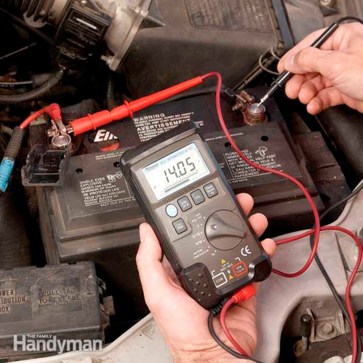
68 block 440. Battery isn’t charging while running. Battery is new - had to use jump box to start and get car home after a show - car had an hour or so of run time - car died on me in gear and had no juice.

Testing now in garage - with ignition off - voltage is same on both sides of voltage regulator, battery, and back of single green wire terminal on alternator (roundback style) Field wires on alternator stud show 0 at ignition off. When ignition on field wire stud shows some voltage.

Any suggestions? Thank you.

IMG_6024.jpeg


IMG_6025.jpeg
 
I assume the testing you speak of was with the alt and voltage regulator mounted and battery fully charged ? Pix don't show that alt and regulator are mounted... The green wire on the alternator is the field connection from the voltage regulator. The case of the regulator must have a good ground to the firewall. The stud on the alternator is basically connected to the battery. it passes thru the alt gauge in the dash and that path comes and goes thru the bulkhead connector This is assuming you have not modified the electrical bypassing the alt gauge and bulkhead connector as some folks do.
The case of the alternator gets it's ground via mount to engine. The engine should be tied to ground ( Battery- ) via the ground strap from battery minus to the block. There should also be a ground strap from engine to the firewall. It's possible that the alternator and or voltage regulator are defective. Also inspect the wiring at the bulkhead connector for signs of burnt connections or signs that wires have overheated. I would suggest going to a solid state modern voltage regulator vs. the old school mechanical one you have, they are more reliable. The alternator has diodes internal that can drain the battery if defective. Good luck with solving your problem..
 
Thanks. I took the voltage regulator off the firewall to inspect the back side.

I just removed the alternator after testing a few minutes ago to get easier access.

Have a ground strap to block already. Don’t see any other grounding wire directly from VR to block, however.

I will check bulk head and also the wires to the amp gauge as well if they are tight. Anything else?

Thank you.
 
What is the voltage at the battery while it’s running?
 
Usually there is a ground strap from passenger side rear of block to the firewall. You may have another path from battery minus to the chassis. The regulator case gets it's ground by attachment to firewall, there is typically not a separate ground wire for the regulator.
 
1. fully charge battery
2. clean both terminals of battery and batter cable VERY well
3. with car off, voltage on + and - of battery should be a little over 12 volts
4. with car running, voltage on + and - of battery should be over 14 volts
5. with car running & everything connected, the terminal of the green wire should be 5V, or 7V or 12V...can't remember, I think 12V
6. with car running and everything connected, the big terminal of the alternator should be over 12V. Use the alternator housing as your ground connection.
7. with car off, check for ohms between big terminal of alternator and + of battery. It should be a really, really low number

A factory service manual will have a step by step diagnostic test in it
 
With your car running, remove the negative cable. If the engine keeps running, your alternator is working OK. If it quits, something is wrong with your charging system. If you are running an electronic ignition system, you should replace the mechanical VR with a solid state one. The ECU does not like "spikey" electricity as produced by the mechanical VR. The mechanical VR has two fusible links inside, so a fusible link wire should be added to the circuit if replacing the mechanical VR on early cars.
 
With your car running, remove the negative cable. If the engine keeps running, your alternator is working OK. If it quits, something is wrong with your charging system. If you are running an electronic ignition system, you should replace the mechanical VR with a solid state one. The ECU does not like "spikey" electricity as produced by the mechanical VR. The mechanical VR has two fusible links inside, so a fusible link wire should be added to the circuit if replacing the mechanical VR on early cars.
If the VR is fine......could I damage the VR by removing the negative battery cable while running?
 
Thanks everyone - will follow everyone's advice and see what happens - thank you!
 
Pop the top on the VR and inspect for burnt leads inside.
 
1. fully charge battery
2. clean both terminals of battery and batter cable VERY well
3. with car off, voltage on + and - of battery should be a little over 12 volts
4. with car running, voltage on + and - of battery should be over 14 volts

Going down your list - Initial startup battery was around 12.4/12.5 volts - while running it dropped slightly to 12.3/12.2…..
 
5. with car running & everything connected, the terminal of the green wire should be 5V, or 7V or 12V...can't remember, I think 12V
6. with car running and everything connected, the big terminal of the alternator should be over 12V. Use the alternator housing as your ground connection.

So with car running - battery voltage stayed at low 12s.

Green wire on back of alternator - it’s hard to get at, but poked around and didn’t get any reading of voltage while car was running.

Bottom stud terminal of alternator in the right spot it would read 12 volts while running.

Assuming if above is all correct - voltage is getting to alternator but voltage not going from alternator to battery?

Thanks guys.
Not exactly.... that indicates that your alternator is not charging BECAUSE the field wire (the smaller green one) doesn't have 12v/5v (can't remember). That green "field" wire is what turns your alternator on & off. Trace the green wire back to where it comes from and also check to see if that wire is broken or pinched somewhere. I'm going from memory, but I "think" that green wire comes out of the voltage regulator (check a wiring diagram)....so broken green wire, bad voltage regulator or bad ground (case of voltage regulator to voltage regulator bracket to body of car). So...
1. disconnect the green wire on both ends (alternator and voltage regulator). Using a multi-meter, check for ohms on that wire. The ohms should be "almost" zero....like 0.03 or something. If ONE or "no continuity" on your multi-meter, replace/fix the green wire. You can clean the terminals (green wire and alternator) while you're at it.
2. if test #1 passes, with key "on" check for 12V going into the voltage regulator on the BLUE wire. It's the other wire on the plug on the voltage regulator you unhooked to run test #1. If you have 12V on the blue wire, then replace the voltage regulator ($20 and a common Mopar problem). While you're at it, sand or wire brush the connection points on the voltage regulator bracket AND take the bracket off and scrape a little paint of off where the bracket bolts to the body. This will make SURE the voltage regulator is grounded.

If you wanted to get "fancy", before replacing the voltage regulator, take some jumper cables, and using only ONE cable (e.g. black/black only)...connect one black to the body of the voltage regulator and the other black end to the negative of the battery. You don't need the red cable at all. That's another way to be SURE the voltage regulator is grounded before you replace it.

3. If still not charging, then start tracing the blue wire for power. If you have a "double" ballast resistor, sometimes just one side will burn out.

When the alternator is working & the car is running, you should have about 14.6V between the + and the - of the battery
Your #3 response re the dual ballast resistor.....it has nothing to do with the alternators field and voltage regulator circuit. Consider using a jumper wire, to TEMPORARILY feed the alternators field brush directly from the battery with the engine running, this will cause the alternator to charge at MAXIMUM. If the alternator charges, the alternator is probably OK. The mechanical voltage regulator you show has 2 fuse links UNDER THE COVER....it is possibly that they are open, causing zero field voltage to the alternator and a no charge condition. Replace the mechanical voltage regulator with an electronic voltage regulator equivalent that resembles the mechanical voltage regulator........just my opinion of course......
BOB RENTON
 
Last edited:
Your #3 response re the dual ballast resistor.....it has nothing to do with the alternators field and voltage regulator circuit. Consider using a jumper wire, to TEMPORARILY feed the alternators field brush directly from the battery with the engine running, this will cause the alternator to chsrge at MAXIMUM. If the alternator charges, the alternator is probably OK. The mechanical voltage regulator you show hasc2 fuse links UNDER THE COVER....it is possibly that they are open, causing zero field voltage to the alternator and a no charge condition. Replace the mechanical voltage regulator with an electronic voltage regulator equivalent that resembles the mechanical voltage regulator........just my opinion of course......
BOB RENTON
So like this one?

Screen Shot 2023-07-19 at 9.33.03 PM.png
 
Your #3 response re the dual ballast resistor.....it has nothing to do with the alternators field and voltage regulator circuit. Consider using a jumper wire, to TEMPORARILY feed the alternators field brush directly from the battery with the engine running, this will cause the alternator to chsrge at MAXIMUM. If the alternator charges, the alternator is probably OK. The mechanical voltage regulator you show hasc2 fuse links UNDER THE COVER....it is possibly that they are open, causing zero field voltage to the alternator and a no charge condition. Replace the mechanical voltage regulator with an electronic voltage regulator equivalent that resembles the mechanical voltage regulator........just my opinion of course......
BOB RENTON
What he said..... sounds correct. A TEMPORARY field hot wire sounds like a great idea
 
Disconnecting the ground wire while the engine runs does not always indicate a "good" alternator. Some of the diodes could still be bad.
Battery must be completely charged before any testing.( with a battery charger, not the alternator)
Needs to show at least 12.5 volts static before load testing. Less than 9.6 volts under load indicates bad battery.
13-14 volts when running is good.
Click and completely read/watch these articles for more details.
 
The FIRST thing I always do in a no-charge/discharge situation, when I believe the battery is good, is to momentarily full-field test the alternator to rule it out as a suspect. More often than not it turns out to be an alternator problem. Quick, easy and...free!
 
Auto Transport Service
Back
Top