• When you click on links to various merchants on this site and make a purchase, this can result in this site earning a commission. Affiliate programs and affiliations include, but are not limited to, the eBay Partner Network.

Dash wiring on 62 dart

62phoenix

Active Member
Local time
9:00 PM
Joined
Nov 28, 2012
Messages
37
Reaction score
5
Location
Western Australia
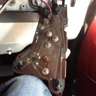
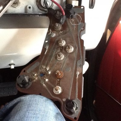
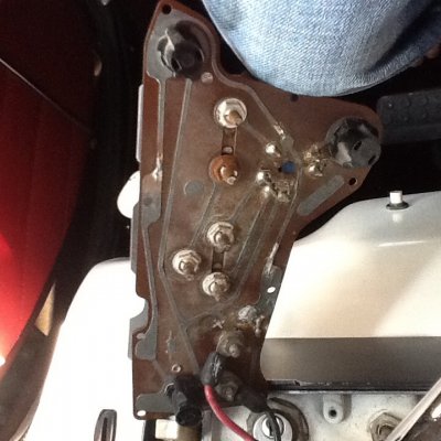
Pics from the back of the circuit board on my 62 Dodge Dart...this is the Aussie version that runs the same dash as the Plymouth signet.
It has no fuel or temp gauge working but the ammeter does work. The dash lights were always on when the car runs!

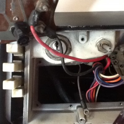
Stray wire....missing a volt limiter and condenser? I have nothing to go on with this as I can't find specific diagrams of photos to use as a referance.

Any advice would be great.

- - - Updated - - -
 

Attachments

  • image.jpg
    image.jpg
    162.6 KB · Views: 501
  • image.jpg
    image.jpg
    160.1 KB · Views: 400
Last edited:
not a clue, but you might have better luck over on For A-Bodies Only
 
This is the same cluster that is used in the '62 Lancers and Valiants in the US. The voltage limiter is inside of the temp gauge, and feeds both gauge circuits. 12v feeds into the temp gauge terminal closest to the ammeter and limiter voltage feeds over to the fuel gauge on the straight printed circuit trace that feeds over to the fuel guage. You can put a voltmeter on that trace with the key in the RUN position and see if you have a pulsed voltage there.

The dash lights being on all the time are a short somewhere or the dimmer circuit in the headlight switch being messed up.

PM me if you still need more help; I have the FSM on this.


The first thing I would do is try and find a good circuit board,I see places where the printed circuit is actually missing.
 

Attachments

  • image.jpg
    image.jpg
    162.5 KB · Views: 160
DSCN1414.jpg^^ Not seeing any missing traces, just some that have been cut and bridged. (Possiblly for troubleshooting...)

Here is a pix form a '62 FSM on the traces; hope this is clear enough.
 
Your printed circuit board is toast. It appears that the voltage limiter in the temp gauge failed and sent 12 volts to the rest of the circuit board. Probably burned up the temp and fuel gauge too. If I were you, I would find a good printed circuit board and both the temp and fuel gauge. I would also eliminate the voltage limiter in the temp gauge and replace it with a digital volt limiter. That way when and if the limiter fails again, it won't burn everything up again. It will only stop your fuel and temp gauge from working.
 
The circled point on the traces is in the ground ground that goes all round the edge of the PCB. Looks like it is still there if you look at the 2nd photo provided by the OP. All the cut and resoldered traces look to be in the ground circuit trace. I am starting to suspect that maybe the ground points around that loop to the chassis are not being made; the power for the limiter heater element could possibly flow backwards through the instruments lamps try to find a ground. When the cluster ground is not good, all sorts of odd things happen.

Not sure I understand how the limiter failing would burn up the ground trace in several spots? Perhaps a short in the heating coil to ground?
 
thank you to every1

A big thanx to all the posting on this topic...I managed to get a new dash circuit board and a NOS gas gauge.


I also got a solid state limiter to wire in...I'm a little unsure of how I should wire it in...I have 3 wires from it. 1 power in. 1 ground and 1 to attach to the gauges.

Can someone tell what wire I should place where?...the ground is obvious of course!
 
Not near my book 'til tomorrow. If the old voltage limiter is inside the temp gauge (as per the US FSM), then that has to be removed before you can use the new solid state limiter. Unless you want to run the temp gauge from the old limiter, and the fuel gauge from the SS limiter. What is your plan for that?
 
I have disconnected the old temp gauge limiter so its all going to run from the new solid state one.
 
OK, did you get the info on hook up you needed? I have been working and traveling like crazy....
 
Auto Transport Service
Back
Top