• When you click on links to various merchants on this site and make a purchase, this can result in this site earning a commission. Affiliate programs and affiliations include, but are not limited to, the eBay Partner Network.

Degree an installed/unknown camshaft

I think you cam is 108 so you have to adjust

As AJ/FormS mentioned, they want it installed at 105*, which is 3* advanced.
I measured 106*, which will be straight up for me as there is no way for me to adjust the cam 1*, and considering i f*cked up a bit with measuring that needs compensating for.

Now; working from this figure
[email protected], and 238/2 less14=105 the installed centerline of the intake lobe
[email protected], and 244/2 less11=111 the installed centerline of the exhaust
105 plus 111 divided by 2 = 108 the Lobe Displacement angle. And in this case they want it in at 105 which would be 3 degrees advanced.
 
Intake lobe is 36+69+180=285 @.008, and 285/2 less 36= 106.5 installed CL of the intake valve
Exhaust lobe; [email protected], and 291/2 less 39=106.5 the installed centerline of the exhaust valve
106.5 plus 106.5 divided by 2= 106.5 the Lobe displacement angle; using your numbers. And you are in "straight up", at zero advance; so, time for a compression test. I'm very excited,lol.

I like where it is. It is very very close to straight up. It is not advanced. Straight up is zero advanced, is, with your numbers, 106.5.
The intake is in at 106.5* ICL and the exhaust is also in at 106.5* ICL. This can only happen (that they be the same) , if the cam is in straight up.
If the cam was advanced 5* then it would read 101.5 ICL and the exhaust would read 111.5 ICL. Then; 101.5 plus 111.5, divided by two, again makes 106.5 Those two always work out this way.
I think you are confusing LDA (Lobe Displacement Angle) with ICL (Installed centerline.)
The LDA is ground into the cam and cannot be changed during installation. Yours is 108 by the Hughes numbers and 106.5 is what you measured
The Intake ICL is what you can change and generally varies from the LDA;by up to 6 (or maybe 8*) advanced which using your numbers,would read; 106.5 less 6=100.5
According to your numbers; the Intake ICL is the same as the LDA, therefore it is in straight up, zero advanced. It cannot be otherwise. Even if the lobes are not symmetrical, you have the Exhaust ICL also as a second witness.

If you advance it from here, the pressure will go up.
If you retard it from here, the pressure will go down.
That is the main purpose for moving the cam, too manipulate the pressure. More pressure builds stronger bottom end. Less pressure softens bottom end.
Your pressure was waaaay too high for your gasoline, so it had to be reduced. But your VP was also far too high for a street-chassis to do anything with except spin the street- tires.
At the new pressure, you WILL notice the pressure loss at zero mph, there is no denying that. But it's like squirrel hunting with a bazooka; how dead do you need the squirrel to be? ; if a VP of 150 spins your tires all the way thru first gear, do you really need 160 or more?
On the flip side, your power peak will be moved up considerably, and with the rpm comes more power in the midrange and especially at the top. This you will also notice. 4* is easily felt with your butt-dyno. Imagine a 13 degree change. When you hit second gear at WOT; hang the heck on!
BTW; You will need a new tune.
 
Last edited:
LDA is the same as LSA? Lobe Separation Angle?
Because i think i cannot handle any more names/specifics about camshafts by now :D

As you mentioned, Hughes specified an LDA 108, i measured 106.5.
Would that be measurement error or could there really be differences of 1.5* in a grind?
I assume all these cam grinds are CNC machined and should be very accurate.

BTW; You will need a new tune.
I think you already covered the first episode of that. :)
And then, i think this time it will be easier than i was used to.

Tomorrow a next session of compression testing, i will get a valve spring compressor and some checking springs to use.
Was i right by how to check the PV clearance? Could use a dial gauge on the rocker arm to see what distance the valve is from the piston while pushing it down by hand at 5* crank intervals?

After i will get the engine prepared to remove and next time i am home pull it out and get some **** done!
 
comments in the quote
LDA is the same as LSA? Lobe Separation Angle? Oh yeah I forgot; LDA seems to have fallen out of vogue,lol. Yes, the same
Because i think i cannot handle any more names/specifics about camshafts by now :D

As you mentioned, Hughes specified an LDA 108, i measured 106.5.
Would that be measurement error or could there really be differences of 1.5* in a grind?
I assume all these cam grinds are CNC machined and should be very accurate.
No the error is probably a combination of the angle at which your equipment was, relative to perpendicular, in conjunction with the concave surface of the upside down lifter. This is more common than you might think. The indicator tip is a ball and if it rides up/down the concavity of the upside-down lifter, it skews the reading. If the indicator is not positioned on a parallel line to the lifters direction of travel; this will also skew the readings. And finally, if your TDC pointer is 2 degrees wide and on top of the degree wheel, then you have to estimate the reading. If you estimate down one time and up the other time, well there is 2 degrees right there.


I think you already covered the first episode of that. :)
And then, i think this time it will be easier than i was used to.

Tomorrow a next session of compression testing, i will get a valve spring compressor and some checking springs to use. I was unable to use that type of compressor on my heads, there was no getting under the springs with it. I used this; from Hughes cuz that's where I was buying my new cam It worked well on my new HD valve springs that I ordered with the cam.
com5324.jpg

Was i right by how to check the PV clearance? Could use a dial gauge on the rocker arm to see what distance the valve is from the piston while pushing it down by hand at 5* crank intervals? Yeah I think that will work. To make it go quicker start with the piston at TDC on the exhaust stroke, and check that exhaust valve. Then turn the engine over backwards CCW from the front, until the minimum is discovered. If it is increasing, then go forwards, CW.
Millers method would be faster if the engine was out and you had flat-top pistons.
But I don't know if your engine has flat tops in there, and if not then the valves are gonna be down in the valve pockets and probably hard to access.
But then; if the engine was out, you could easily measure the total chamber volume by just pouring a light oil into it from a graduated container.

After i will get the engine prepared to remove and next time i am home pull it out and get some **** done!
 
Last edited:
Witese
you have an Engle K-60 grind on the Intake and K-62 on the Exhaust
The Hughes Number HE 3844 equals 238 duration Intake and 244 duration Exhaust which matches the Engle duration and lifts within a degree and a thou
Engle had the timing as 52 12 on the Exhaust and a degree difference in duration but
that is what it is supposed to be with a NEW grinding wheel
when they get worn timing and duration can change slightly-
you are so close as to be golden
The intake as a duration of 152@200 and the Exhaust 156
whereas the DC-MP 284 cam I checked had 143 @200 for both lobes as it was a single pattern grind
so you can see the Engle is quite a bit fatter (and both still wear well)
many on this board may be more familiar with the Direct Connection Cam
they should idle the same and have about the same vacuum but you will have more torque and a slightly extended rpm range with the longer than DC exhaust
The Engle lobes ARE Asymmetrical but not radically so
BIg cam
now let's make it work
cheers
as far as the Lobe Centers 108 or 107 makes no real difference
Engle usually grinds those grinds at 108 but Hughes could have specked something different
or
it could be the worn grinding wheel tolerance stacking and your measuring
whatever it is be happy
These are NOT CNC grinds old school hand ground and not CNC masters either
Engle grinders have 20+ years of experience
I would think that if you had gotten the cam direct they would give timing off the post grinding cam comparator
for this post an actual Engle cam card was reviewed for a BBM with these grinds
 
Last edited:
So LDA is from early days and LSA is the modern name. :)

Actually, i did make a run with the solid lifter upside down but that did not work out as when the cam lobe comes near the highest lift point it dropped, and raised again as the cam nose kinda went inside the hole in the lifter so i put it back to normal to complete the run.

Think i will give that compression tool a try, if the feet don't fit inside the spring i can make some modification to make it fit i guess.
Also need to make up an adapter to connected an airline on the spark plug hole to keep it pressurized.
When doing this, should i keep the piston near TDC and secure the crank against rotation?
If for some reason i do drop the valve after removing the spring it cannot go far.

Is there a way to determine the effective rpm range of this cam?
Comparing it with similar cams it seems it should be around 2300-6200 rpm.

that is what it is supposed to be with a NEW grinding wheel
Yeah that's true, forgot about the point they actually use a grinding wheel.
It is obvious when that wears out slightly the lobe will slightly change as well.
 
also LCA
but what we need to concentrate on only is the Intake Center Line ICL
which with an Asymetrical cam is really just for a place to install to and may or not be the actual exact center line
where is the Centerline?
the center line of the peak of the lobe down.050 timing
or the center line of the base of the lobe .050 timing
does not matter at this point
stick it in at that around 106 mark and looking foreword to you new compression figures
BTW I have not done the math but I think Aj must have meant 106.x BTDC for the Exhaust
having them the same is more than coincidental but not to worry about it
 
where is the Centerline?
the center line of the peak of the lobe down.050 timing
or the center line of the base of the lobe .050 timing

I would say that with an Asymetrical cam lobe the center should be more exact when taking it from the peak of the lobe. That is where the max lift point is being centered.
From the base line you are including the difference in ramp up/down.
 
stick it in at that around 106 mark and looking foreword to you new compression figures

That's where she is at now, 106.5*, will see tomorrow what cranking pressure this is going to give.
If all goes well and pressure dropped to 165-ish that would be good i guess.
Hope that means i can get my 3.55 gears at the near future as well then :)
 
wyrmrider; nice data.
Thank you for your generosity in providing such valuable information, for absolutely no charge.
 
That's where she is at now, 106.5*, will see tomorrow what cranking pressure this is going to give.
If all goes well and pressure dropped to 165-ish that would be good i guess.
Hope that means i can get my 3.55 gears at the near future as well then :)
Hold on there Bubba; It's in at 106.5 ......using your numbers, which puts the cam straight up in reality.. In Hughes numbers straight up is 108. Wyrmrider said 106 which would be 2* advanced,lol.
IMO, just leave it where it is until we see what has happened to the pressure. THEN you can decide if you want to change it.
 
Last edited:
Ok, some updates:
Cranking pressure is now 160-170 PSI, checked on cyl #1 and #2.
So, very good it has come down a bit from 180-185.

The story of where the centerline is, measuring from base line and from the nose made me wonder.
I measured again, from both points and found the following:

Exhaust:
Base line: @ 0.050" . Centerline: 109*
Valve open: 51* BBDC (53)
Valve close: 13* ATDC (11)

Cam nose: @ 0.050" . Centerline: 109,5*
Valve open: 26* ABDC
Valve close: 65* BTDC

Intake:
Base line: @ 0.050" . Centerline: 108*
Valve open: 11* BTDC (14)
Valve close: 47* ABDC (44)

Cam nose: @ 0.050" . Centerline: 105,5*
Valve open: 33* BBDC
Valve close: 64* ATDC

In between brackets as per cam specs.

As per baseline readings it is straight up with the ICL being at 108*, same as the LSA.
As per the 0.050" readings of the cam specs the IC should be at 105*
The nose is actually at 105*, so i guess the tip for this will be DO NOT TOUCH!
 
Last edited:
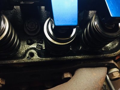
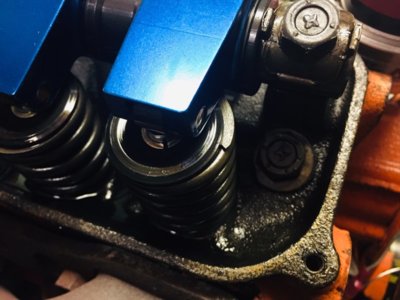
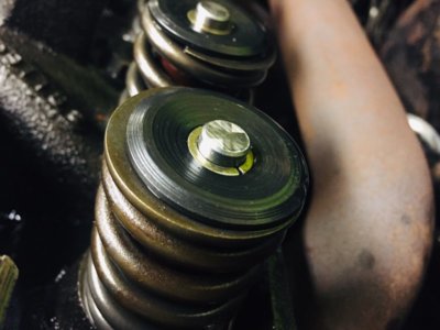
I had seen this before but now i am wondering is this ok?
It seems that the valve spring retainer cups are too small.
The outer spring has an O.D. of 1,5" but the cup is less, the cup should be bigger i think?

IMG_3576.jpg IMG_3577.jpg
 
Evidently Engle and Hughes both use the .050 up from the base method to degree in the cam so go with that
cam is asymmetrical so here the pointy nose is earlier-
remember where max lift is, the Intake lobe center(middle of the down intake stroke) is meaningless as far as how the motor will run
but where the Intake closing is a key factor
your cranking is good enough for a test run- right AJ?
Yep on the retainer vs spring size did they come as a matched set?
other eyes need to take a look at this
are the bottoms of the springs positively located (machined cups)
 
did they come as a matched set?

No idea, came with the car.
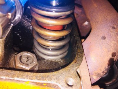
They seem to sit straight on the cylinder head, there is no cup on the bottom side.
Inner spring coil seems to be made from a flat bar type spring instead of round material.

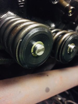
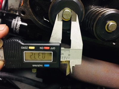
Edit: Another weird thing, just measured the tip of the valve stem, 0.371".
Obviously one of the weird sizes instead of something standard.
Could just replace the valve spring retainers with some correct size keeper, just need to wait until i have removed a set and i can do some decent measurements on what i need.

IMG_3579.jpg
 
Last edited:
Ok perfect leave the cam right where it is for now. Then see, If after the WOT timing has been established, if your best gas can handle the pressure without detonation. If it can without detonation,then you can try the next lower grade of gas. If there still is no detonation; then, if you found the low-rpm too soft and wanted to, you could advance the cam to increase the pressure because you now have some room to do that. Wait until the new tune is in.

As for the retainers;there is definitely a mismatch there.You'll be able to figure it out after you get one off. But before that, center the spring up underneath it, and make sure the rocker arm does not contact the spring or the retainer anywhere in it's travel. With 1.6 arms, clearance under there is usually at a premium. Also, If it was mine, I would have the springs pressure tested to see if they are correct or even adequate for your cam and 1.6 arms.

And while you are doing all this, you might as well check your geometry.
 
Ok, some updates:
Cranking pressure is now 160-170 PSI, checked on cyl #1 and #2.
So, very good it has come down a bit from 180-185.

The story of where the centerline is, measuring from base line and from the nose made me wonder.
I measured again, from both points and found the following:

Exhaust:
Base line: @ 0.050" . Centerline: 109*
Valve open: 51* BBDC (53)
Valve close: 13* ATDC (11)

Cam nose: @ 0.050" . Centerline: 109,5*
Valve open: 26* ABDC
Valve close: 65* BTDC

Intake:
Base line: @ 0.050" . Centerline: 108*
Valve open: 11* BTDC (14)
Valve close: 47* ABDC (44)

Cam nose: @ 0.050" . Centerline: 105,5*
Valve open: 33* BBDC
Valve close: 64* ATDC


In between brackets as per cam specs.

As per baseline readings it is straight up with the ICL being at 108*, same as the LSA.
As per the 0.050" readings of the cam specs the IC should be at 105*
The nose is actually at 105*, so i guess the tip for this will be DO NOT TOUCH!
Once again;
the cam is not straight up in my estimation, because if it was then the exhaust would also be 108 because 108 +108/2=108

But in your case; you have what appears to be 109.5 +105.5/2=107.5
If your intake is at 105.5, then you are 2 degrees advanced from the LDA of 107.5.

But like wyrmrider says; it's really not important cuz you have determined the Ica to be 65* ATDC.. But here we go again; your chart says this is at .050 which is impossible.

Your numbers are 33 +64 and to this you have to add 180 for a total of 277 intake degrees. since we have determined this cam to be a 285/297/108, your number do not jibe with the .008 lift figures, and so you cannot use the 64*ICA as being accurate. It may be correct for some other loft figure but not for .008 tappet, IF we have the cam properly figured out. So this is what we are working from;
So it's a Hughes Engines HE3844 BL camshaft.
upload_2019-8-20_14-43-48-png-png.png

upload_2019-8-20_14-39-34-png-png.png


Notice the intake closing point is called to be at 44*ABC @.050 tappet lift.
If I read your numbers correctly, it says you have 47*
That would be 3* later or 3*retarded.

IMO you got too many numbers and I can't tell what's what anymore.
But I'll tell you what; I 'll get you a Wallace result using 165psi and the Hughes 44*, which I am gonna arbitrarily gross up 46*/2, to get the approximate Ica of 67*, What do you think wyrmrider will that be close, for .008tappet rise?
Here it is

Static compression ratio of 10.4:1.
Ica estimated to be 67*, and at sealevel
Effective stroke is 2.83 inches.
Your dynamic compression ratio is 8.09:1 .
Your dynamic cranking pressure is ................165.96 PSI.
V/P of................................................ 165VP

There you have it [email protected] Scr and VP is a killer 165. This is an estimate until you can show an Ica measurement at .008 tappet rise.
But it looks pretty good right now.

Just for kicks, lets plug 10.4Scr into the calculator, and 67* less 13*=54* Ica the earlier intake closing number, and see what kindof pressure the calculator spits out.
And I get
Static compression ratio of 10.4:1.
Ica of 54* @sealevel
Effective stroke is 3.15 inches.
Your dynamic compression ratio is 8.90:1 .
Your dynamic cranking pressure is ................... 187.87
PSI.
V/P (Volume to Pressure Index) is ................... 208
That matches up pretty close to post 152, and

In any case you are now on the right track..... I think. Because 165psi is doable, if they all average down to that, or lower.
 
Last edited:
The measurements given there are also including 0.050" measured from the top of the lobe, which in case of an asymetrical design i can figure will not be in the middle compared to the 0.050" from the base line.
Could that not cause the confusion?
Because on the base line measurement of 0.050" it is at 108*

I just went 2 rounds and checked the 0.008" lift on the intake lobe.

Valve open @ 0.008": 35* BTDC
Valve close @ 0.008": 69* BTDC

I also redid the readings at 0.050" from base line.

Valve open @ 0.050": 13* BTDC
Valve close @ 0.050": 45* BTDC

Guess the more times i go around the more variation we are getting, it is not consistent but very close.

Edit:

These are the numbers from the previous run. Post #123

Intake valve @ .050"
Open: 13* BTDC (14*)
Close: 44* ABDC (44*)
Centerline: 106*

@ .008"
Open: 36* BTDC
Close: 69* ABDC
Duration @ .008": 285* (283*)
 
Last edited:
Also checked the rocker arms but there is no evidence of contact with the spring or retainer at all.
As can be seen in the pictures, the geometry looks good.
I will ask my engine builder who is doing a VW 1.8 engine for me now if he can check the spring pressure test.
Valve stem came out to be 0.372"

Edit: How do you calculate the ICA? What is that exactly then?

IMG_3580.jpg IMG_3581.jpg IMG_3582.jpg
 
Last edited:
Auto Transport Service
Back
Top