Propwash
Well-Known Member
- Local time
- 9:49 AM
- Joined
- Oct 29, 2009
- Messages
- 9,695
- Reaction score
- 4,338
- Location
- Island of Misfit Toys
Hey guys...Posted this over at my bird's resto thread. Since most don't have time or care to to go through that novel and there's been a lot of questions about lighting going on around here, though I would share in this section..
HID Conversion
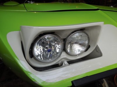
So, sick and tired on the old yellow dim headlights that sink like a dying candle at stop lights. The bird had received a lot of modern upgrades so why stop at the lights? I'll try to make this write up as easy as possible so if folks want to follow the same or a similar route down the road, maybe it would help them out.
Went back and forth in between a Halogen or HID upgrade. IMO, HID happens to have more pro's than halogens after reading many articles, posts, a book and reviews. This includes being brighter, running cooler, sucking less power, living longer and having a variable color spectrum to choose from.
Here's what I basically started with for supplies. Some of it is redundant, but gives a general idea

Here's the meat and potato's of it all, the schematic I put together for the relay driven Quad HID lighting system. Follow along on the post and you'll see how it ties all together.
View attachment 99269
This is the HID kit I purchased, bought it off ebay for $35.00 per kit...You'll need two kits for quad lighting. I bought a 6000K H1 and a 6000K H4 kit. 6000k is a diamond white color. Go up to 8000, you're looking at more blue. Go over 12,000, now it's turning a purple like hue. Anything under 5000K, it gets more and more yellow. Reading the reviews of this MFG, there is good and there is bad. Most issues I seen where from people plugging into their original light harness and having flickering and ballast problems. A relay system seems to cure a lot of those issues. There is a lot of reading and reviews on HID kits, so if you're going to make the investment, take your time and research them. i'm hoping to be happy with mine, but just don't have the experience with them yet to give an accurate review.
View attachment 99270
So tearing into stuff...I needed a place to mount the ballast so I chose the front of the radiator core to the sides. They're waterproof with waterproof connections and I could disguise them behind the front grill fill panel. Problem is, the length of the harness from the bulb to the ballast on the outer low beams...not long enough.

I think most around here has a pretty good idea what a good butt or splice connection is. Just to throw in the history of this thread, every butt or splice connection in this wiring, I used un-insulated butt connectors from Radio shack. Once crimped, I applied lead free electronics solder to each connection, covered with heat shrink and then was covered by decent electrical tape. Do this and you don't have to worry about electrical connection points being a place to corrode and/or fail/cause a fire down the road.


As far as the Electrical tape...Most of the system I went with Scotch Supper +33, which is an excellent vinyl electrical tape. A couple spots I wanted to replicate the cloth look from the factory. "Duck" brand tape sells a friction tape that not only holds and protects well, but looks like the cloth original.

Relays......With my HID system, you'll need (2) 5 Pin 40 AMP Dual 87 relays. I bought Hella's because they're a good name in lighting...HELLA H41010001 Dual 87 40 Amp SPST Mini Relay with Bracket. Here's where I actually found them:
http://www.discountfleetsupply.com/helh41010001.html

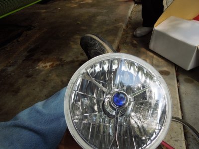
This place was great to deal with. Was fast and one of the cheapest! I also Bought my Hella H4 and H1 headlamps from them. Cheapest I could find anywhere.
View attachment 99271
View attachment 99272
http://www.discountfleetsupply.com/hel002425831.html
http://www.discountfleetsupply.com/hel002850001.html
These 5 pin plug connectors I picked up off Amazon. Pretty easy to find and I went with the 14 GA. wires pre-installed into them. I had to make a change to my 12 GA. power wire running into the relay (slot 30) from the circuit breaker. Used a fine fine screwdriver to push in the little tab of the terminal connector and it popped right out.

The 40 Amp circuit breakers I picked up at Twilight Zone or as some know it, Auto Zone. I went with dual circuit breakers in my system to have somewhat of a fail safe. If something is failing on one side of the circuit and tripping, I'll hopefully have the other to get home.

The HID kit's ballast's unfortunately have no mounting tabs to mount. It comes with some cheap two sided tape and zip ties, which was not going to work for me. So, went down to the hardware store, picked up some 1"W x 1/16" thickness aluminum. These ballasts are very small and very light so I didn't need beefy metal to hold them in place. Cut for length, bent them up in the vise and painted with Eastwood Ceramic Chassis black. I used Locklite two sided tape to hold in place (very good stuff). I also used a dime sized piece of ribbon tape (used on back windows), on the backside when mounting on the car to keep vibration down and to help hold a bit more.


Now, to run a quad beam system with HID's....HID's have a start/warm up period. They just don't come on at full power like regular lights. The problem with this is when you're going down the road with just high beams on and you switch back to low's, well...it's gonna be dim at first. No thanks. To resolve this is to have all four lights on when in high beam..meaning with lights on, either way your lows will be on. The factory lighting was designed this way (quad lighting), using jumpers, but the HID bulbs just run one + and one - wire and you do not want to jump wires forward of the ballasts. To cure this you must install a Rectifying Diode. I bought a 6 Amp...200 and some volt diode at radio shack for this. You want to install it in a jump wire from the high beam signal wire to the low beam signal wire. That way, when you hit the brights, power is sent to the low beam circuit as well. The mission of the diode is when just the low beams are on, it cannot jump past that diode to power the high beams. If the diode wasn't installed all four of your lights would be on no matter what. Be sure to install the diode with the grey stripe (cathode) attaching to the wire that you don't want power coming back down. See schematic above.

So as per the schematic, the relay harness is built. You can see on the ends the connectors that plug into the Ballasts. If you're wrapping your harness, mark the plug ends with a label or paint marker so you know which is which.

Now to integrate it into the factory Harness....This harness was out of a '68 Dodge. Had some extra wires my roadrunner did not, like for side marker lights and hood mounted turn indicators. The wires I needed to worry about keeping was the wires for the low beam selector (violet), high beam selector (red), yellow wire to the starter relay, brake warning switch wire (black) and the wires for the turn signals.
http://www.mymopar.com/downloads/1969/69BelvedereGTXSatelliteRoadRunnerB.JPG
Removed wires:

With the factory harness tied into the relay Harness:

As far as the relays, if you're running a decent Stereo, you'll need to run a diode across from your 85 to your 86 pin on your relays. This is not isolated to HID's. This is isolated to using a relay type system. You can end up with electrical interference over the airwaves if not doing so. I ran a very small 1AMP 50V diode on each relay.

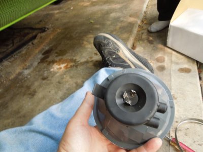
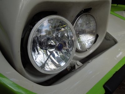
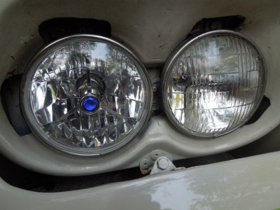
I need to update you guys with some pic's here in the very near future. The harness is in the car...the h1 High beams lamps are installed already and about to install the H4's. Good news is I hooked up a battery to this set up, running through the bulkhead, and everything works just as it should. The Hella lamps fit well in the buckets and the headlight trim/retaing rings hold the lamps in place nicely. As soon as it actually gets over 0*F and I get a little time, I'll snap some for you.
On closing this portion (with Pic's to come), I hope this helps someone else down the road. There are some things that could be different like; running inline fuses or fusible links or running a Single bigger circuit breaker instead of a double. You could also apply this to make a Halogen system instead of HID. Just run the wires that would be going to the plugs for the HID ballasts to the Halogen bulbs instead. I would recommend you upgrade to a 12GA. wire all around forward of the relays instead of the 14, being there's more continuous power draw and heat. Also, use ceramic connections at the plugs. As far as the HID, they draw a lot less, besides start up. Going off of info from Swede, on start up HID ballast can draw up to 15 AMPS each for 3-5 seconds and then dramatically goes downhill from there. That's why I went with 40AMP relays/breakers.
Like I said....Lights on pic's to come here in the near future.
HID Conversion
So, sick and tired on the old yellow dim headlights that sink like a dying candle at stop lights. The bird had received a lot of modern upgrades so why stop at the lights? I'll try to make this write up as easy as possible so if folks want to follow the same or a similar route down the road, maybe it would help them out.
Went back and forth in between a Halogen or HID upgrade. IMO, HID happens to have more pro's than halogens after reading many articles, posts, a book and reviews. This includes being brighter, running cooler, sucking less power, living longer and having a variable color spectrum to choose from.
Here's what I basically started with for supplies. Some of it is redundant, but gives a general idea
Here's the meat and potato's of it all, the schematic I put together for the relay driven Quad HID lighting system. Follow along on the post and you'll see how it ties all together.
View attachment 99269
This is the HID kit I purchased, bought it off ebay for $35.00 per kit...You'll need two kits for quad lighting. I bought a 6000K H1 and a 6000K H4 kit. 6000k is a diamond white color. Go up to 8000, you're looking at more blue. Go over 12,000, now it's turning a purple like hue. Anything under 5000K, it gets more and more yellow. Reading the reviews of this MFG, there is good and there is bad. Most issues I seen where from people plugging into their original light harness and having flickering and ballast problems. A relay system seems to cure a lot of those issues. There is a lot of reading and reviews on HID kits, so if you're going to make the investment, take your time and research them. i'm hoping to be happy with mine, but just don't have the experience with them yet to give an accurate review.
View attachment 99270
So tearing into stuff...I needed a place to mount the ballast so I chose the front of the radiator core to the sides. They're waterproof with waterproof connections and I could disguise them behind the front grill fill panel. Problem is, the length of the harness from the bulb to the ballast on the outer low beams...not long enough.
I think most around here has a pretty good idea what a good butt or splice connection is. Just to throw in the history of this thread, every butt or splice connection in this wiring, I used un-insulated butt connectors from Radio shack. Once crimped, I applied lead free electronics solder to each connection, covered with heat shrink and then was covered by decent electrical tape. Do this and you don't have to worry about electrical connection points being a place to corrode and/or fail/cause a fire down the road.
As far as the Electrical tape...Most of the system I went with Scotch Supper +33, which is an excellent vinyl electrical tape. A couple spots I wanted to replicate the cloth look from the factory. "Duck" brand tape sells a friction tape that not only holds and protects well, but looks like the cloth original.
Relays......With my HID system, you'll need (2) 5 Pin 40 AMP Dual 87 relays. I bought Hella's because they're a good name in lighting...HELLA H41010001 Dual 87 40 Amp SPST Mini Relay with Bracket. Here's where I actually found them:
http://www.discountfleetsupply.com/helh41010001.html
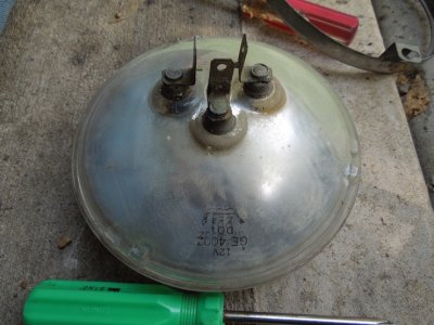
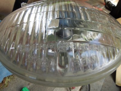
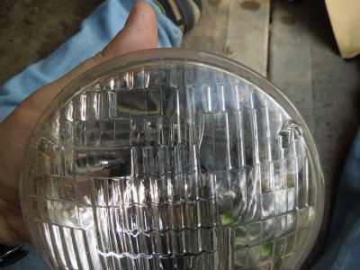
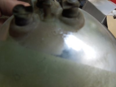
This place was great to deal with. Was fast and one of the cheapest! I also Bought my Hella H4 and H1 headlamps from them. Cheapest I could find anywhere.
View attachment 99271
View attachment 99272
http://www.discountfleetsupply.com/hel002425831.html
http://www.discountfleetsupply.com/hel002850001.html
These 5 pin plug connectors I picked up off Amazon. Pretty easy to find and I went with the 14 GA. wires pre-installed into them. I had to make a change to my 12 GA. power wire running into the relay (slot 30) from the circuit breaker. Used a fine fine screwdriver to push in the little tab of the terminal connector and it popped right out.
The 40 Amp circuit breakers I picked up at Twilight Zone or as some know it, Auto Zone. I went with dual circuit breakers in my system to have somewhat of a fail safe. If something is failing on one side of the circuit and tripping, I'll hopefully have the other to get home.
The HID kit's ballast's unfortunately have no mounting tabs to mount. It comes with some cheap two sided tape and zip ties, which was not going to work for me. So, went down to the hardware store, picked up some 1"W x 1/16" thickness aluminum. These ballasts are very small and very light so I didn't need beefy metal to hold them in place. Cut for length, bent them up in the vise and painted with Eastwood Ceramic Chassis black. I used Locklite two sided tape to hold in place (very good stuff). I also used a dime sized piece of ribbon tape (used on back windows), on the backside when mounting on the car to keep vibration down and to help hold a bit more.
Now, to run a quad beam system with HID's....HID's have a start/warm up period. They just don't come on at full power like regular lights. The problem with this is when you're going down the road with just high beams on and you switch back to low's, well...it's gonna be dim at first. No thanks. To resolve this is to have all four lights on when in high beam..meaning with lights on, either way your lows will be on. The factory lighting was designed this way (quad lighting), using jumpers, but the HID bulbs just run one + and one - wire and you do not want to jump wires forward of the ballasts. To cure this you must install a Rectifying Diode. I bought a 6 Amp...200 and some volt diode at radio shack for this. You want to install it in a jump wire from the high beam signal wire to the low beam signal wire. That way, when you hit the brights, power is sent to the low beam circuit as well. The mission of the diode is when just the low beams are on, it cannot jump past that diode to power the high beams. If the diode wasn't installed all four of your lights would be on no matter what. Be sure to install the diode with the grey stripe (cathode) attaching to the wire that you don't want power coming back down. See schematic above.
So as per the schematic, the relay harness is built. You can see on the ends the connectors that plug into the Ballasts. If you're wrapping your harness, mark the plug ends with a label or paint marker so you know which is which.
Now to integrate it into the factory Harness....This harness was out of a '68 Dodge. Had some extra wires my roadrunner did not, like for side marker lights and hood mounted turn indicators. The wires I needed to worry about keeping was the wires for the low beam selector (violet), high beam selector (red), yellow wire to the starter relay, brake warning switch wire (black) and the wires for the turn signals.
http://www.mymopar.com/downloads/1969/69BelvedereGTXSatelliteRoadRunnerB.JPG
Removed wires:
With the factory harness tied into the relay Harness:
As far as the relays, if you're running a decent Stereo, you'll need to run a diode across from your 85 to your 86 pin on your relays. This is not isolated to HID's. This is isolated to using a relay type system. You can end up with electrical interference over the airwaves if not doing so. I ran a very small 1AMP 50V diode on each relay.
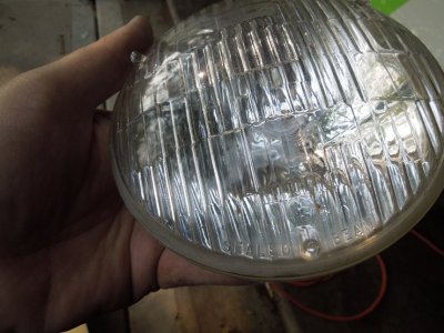
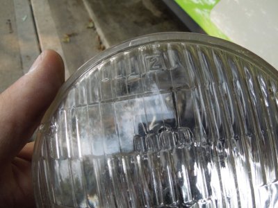
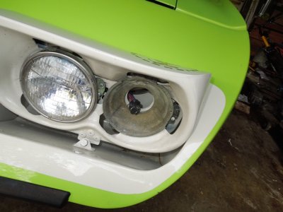
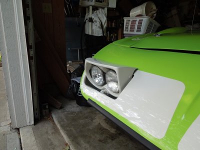
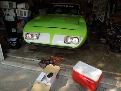
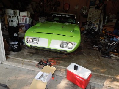
I need to update you guys with some pic's here in the very near future. The harness is in the car...the h1 High beams lamps are installed already and about to install the H4's. Good news is I hooked up a battery to this set up, running through the bulkhead, and everything works just as it should. The Hella lamps fit well in the buckets and the headlight trim/retaing rings hold the lamps in place nicely. As soon as it actually gets over 0*F and I get a little time, I'll snap some for you.
On closing this portion (with Pic's to come), I hope this helps someone else down the road. There are some things that could be different like; running inline fuses or fusible links or running a Single bigger circuit breaker instead of a double. You could also apply this to make a Halogen system instead of HID. Just run the wires that would be going to the plugs for the HID ballasts to the Halogen bulbs instead. I would recommend you upgrade to a 12GA. wire all around forward of the relays instead of the 14, being there's more continuous power draw and heat. Also, use ceramic connections at the plugs. As far as the HID, they draw a lot less, besides start up. Going off of info from Swede, on start up HID ballast can draw up to 15 AMPS each for 3-5 seconds and then dramatically goes downhill from there. That's why I went with 40AMP relays/breakers.
Like I said....Lights on pic's to come here in the near future.