• When you click on links to various merchants on this site and make a purchase, this can result in this site earning a commission. Affiliate programs and affiliations include, but are not limited to, the eBay Partner Network.

ignition/key switch question

What's the voltage at the coil while cranking? I believe IGN2 (brown) sends 12v from BATT to the coil, bypassing the BR when starting. In run position, the BR is back in the cct from IGN1 (blue), reduced voltage to the coil. When I changed to a pertronix system and removed the BR, I forgot to connect the brown and blue together, which acted similar to what you are describing. Don't worry about the GND tab. Some of the accessorized Chryslers, ets, had a ground wire connected to it. If your harness didn't have a wire for it, it should not be an issue.
I'm getting 8.7v at the +coil during cranking. It is 3.7v with engine off and key on. And is 4.3v at idle and climbs maybe to a little over 11v with rpm.
 
I ran into this problem once before, as I recall the solution was 2 wires had to be connected. Its not allowing full contact when cranking IMO.
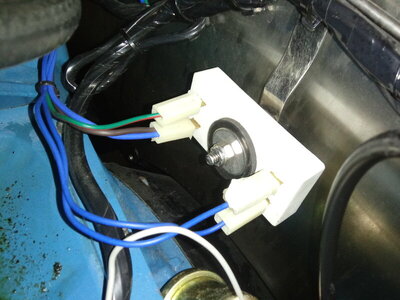
I keep thinking about the ballast and the blue wires on the right side of it. I'm wondering if they need to both be connected together to the bottom of the ballast. I don't think the one on top is going anywhere as is since the green/red wire ends up at the ecu as the unused 5th wire, no pin connector for it on the 4 pin ecu...

20200930_101941.jpg
 
Last edited:
I believe the 5th pin was used in early generations of the ecu. No longer needed with current electronic design. It does look like the jumper is missing between the two blues on the same side. I would pull them off and test with an ohmeter. Also, you should be getting a full 12V (via brown wire) during cranking to the coil. You either have a voltage drop (bulkhead connector?) or the wiring is mixed up.
From a 73 with elec ignition.
upload_2020-9-30_13-42-35.png
 
Found this on another site, might be helpful. I am researching how to connect a stock switch to an aftermarket harness with EFI and I have to have a source that is hot both during start and run..

1---ACCESSORY, hot in both run and accessory, feeds power to the accessory buss in the fuse panel

2--Ignition run, traditionally blue, or "IGN 1". Hot ONLY in run, and NOT in start, feeds power to the cluster gauges, warning lights, ignition and regulator, and a few other things on later cars

3--"Start" wire, traditionally yellow, feeds from the switch, through the bulkhead, to the starter relay and of course engages the relay in "start."

4--The "bypass" circuit, traditionally brown, or "IGN 2". THIS IS probably what has failed. This comes from a separate contact in the switch, through the bulkhead, and to the coil + side of the ballast resistor. It is hot ONLY in start and is THE ONLY source of ignition system voltage during "start."
 
I'm getting 8.7v at the +coil during cranking. It is 3.7v with engine off and key on. And is 4.3v at idle and climbs maybe to a little over 11v with rpm.

this is WRONG... YOU SHOULD get full voltage at coil while cracking, and anything between 4.5 and 9 when in RUN ( ign1 ).
 
Last edited:
I keep thinking about the ballast and the blue wires on the right side of it. I'm wondering if they need to both be connected together to the bottom of the ballast. I don't think the one on top is going anywhere as is since the green/red wire ends up at the ecu as the unused 5th wire, no pin connector for it on the 4 pin ecu...

View attachment 1008594
that's correct, the green traced red wire goes to nowhere on 4 pins ECU modules, but doesn't hurt keeping in place because that allows you to use a 5 pins module in case of emergency from any parts shop around ( if in stock ).
 
I believe the 5th pin was used in early generations of the ecu. No longer needed with current electronic design. It does look like the jumper is missing between the two blues on the same side. I would pull them off and test with an ohmeter. Also, you should be getting a full 12V (via brown wire) during cranking to the coil. You either have a voltage drop (bulkhead connector?) or the wiring is mixed up.
From a 73 with elec ignition.
View attachment 1008620

while tipically is true the blue side having a jumper wire, latelly new repro harnesses are not anymore with jumper but feeding both prongs from same splice down the harness tape, which is the same than get a jumper bewteen both prongs
 
Last edited:
while tipically is true the blue side having a jumper wire, latelly new repro harnesses are not anymore with jumper but feeding both prongs from same splice down the harness tape, which is the same than get a jumper bewteen both prongs


That's why I suggested testing with a meter.
 
while tipically is true the blue side having a jumper wire, latelly new repro harnesses are not anymore with jumper but feeding both prongs from same splice down the harness tape, which is the same than get a jumper bewteen both prongs
I think that may be why I get close to the same voltage on them and everything acts the same with them swapped.
 
this is WRONG... YOU SHOULD get full voltage at coil while cracking, and anything between 4.5 and 9 when in RUN ( ign1 ).
I agree and I did in the recent past, and don't know what has changed and caused this.
I'm going to go over the wiring, bulkhead connector, etc more tomorrow... I went to another cruise-in tonight, about 20 miles away. It ran great and luckily cranked ok when I left. Still firing up as I let off the start position tho.
 
4--The "bypass" circuit, traditionally brown, or "IGN 2". THIS IS probably what has failed. This comes from a separate contact in the switch, through the bulkhead, and to the coil + side of the ballast resistor. It is hot ONLY in start and is THE ONLY source of ignition system voltage during "start."
This sounds like what the problem should be. Will check tomorrow.
 
Found this on another site, might be helpful. I am researching how to connect a stock switch to an aftermarket harness with EFI and I have to have a source that is hot both during start and run.."
I had the same problem finding a source for my fans, since my batt is in trunk I came off the starter relay on the firewall. My fans run anytime I choose, with toggle switch under the dash. No time to work on mine today, maybe tomorrow.
 
Wiring is a process and you really have to understand how everything works and interacts with other things. I rewiring an entire 69 ply wagon for a client/friend with a generic eBay harness and it is a challenge trying to make everything work correctly. I really have to understand how each switch works, where it gets power and when. Its kind of a pain but not too bad, just very slow and tedious.
 
The electrics of my toys has made me scratch my head for 60+ years. One problem on my 68 charger is that I rewired it myself a few years ago after rebuilding the car from junk. The under dash harness is original but most all else is new. The engine bay harness is an m&h conversion that upgrades for later stock style e-ignition and a dual field alternator. I did the ammeter bypass mod, batt in trunk mod, e-fans, and starter jumper wire mod,. so I've made the electrics of this car a nightmare to try to ensure they're correct. I'm not giving up tho, like you said one switch/circuit at a time.
 
Last edited:
I had the same problem finding a source for my fans, since my batt is in trunk I came off the starter relay on the firewall. My fans run anytime I choose, with toggle switch under the dash. No time to work on mine today, maybe tomorrow.
That's wrong if you are keeping the ammeter in place. Everything on our cars with ammeter in working order must be sourced from alt side.

(Editing: nevermind, just read you bypassed on the next reply LOL )
 
Do you have a Power Probe? Greatest electrical tool you can buy.
No, just a cheapo harbor freight freebie multimeter. May have to find one of those. Like this one?>

c23e9936-7b5f-422c-8ce2-18525a3c9e3d.d9a4b251a993427ef18c139dd0186c3d.jpeg
 
Last edited:
Yes like that, they make a wide variety of versions with different attributes and capabilities but a base one (like the one you posted) will do pretty much everything you generally would need. They allow you to apply power to a wire or circuit or determine if there is power on a wire or circuit. As an example, say a tail light is out, the power probe will allow you to test the light bulb by applying power to it and it will allow you to determine if there is power coming out of a wire. It lets you find shorts, hot wires, grounds, etc. Every Mopar guy should have one. Oh and it also will tell you how much juice the battery has or what the out put of the alternator is. They are awesome.
 
Auto Transport Service
Back
Top