• When you click on links to various merchants on this site and make a purchase, this can result in this site earning a commission. Affiliate programs and affiliations include, but are not limited to, the eBay Partner Network.

Installing Classic Auto Air in a '70 Charger

Kern it is very impressive that you have addressed this setback in short order in only a matter of days! Way to go man. Thanks for all the updates. You are way ahead of me on your AC install by the way.

I bought a condenser with the drier pre-mounted. I had it mounted on the driver side and mounted the condenser in front of the rad on the grille side. Will this enable me to keep my metal lines shorter? I am assuming your long run lines from the driver side across the front then to the passenger side firewall are due to your chosen drier location?

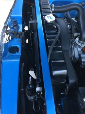
What you see in my photos below on the grille side are the long condenser with pre-mounted drier and the trans cooler mounted on the passenger side in front of that.
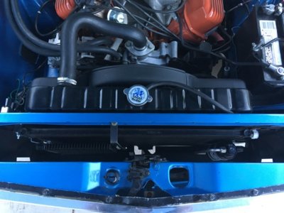
27E84525-7707-4292-99E3-5A86FF636D87.jpeg C82B1E6A-95B9-4034-A741-F30B9CA6406F.jpeg
 
Last edited:
You will still have a line running from the drier to and through the firewall to the under-dash evaporator unit. The drier being behind the grill looks cleaner but you still need to get the freon to the inside!
Summit has all sorts of aluminum lines to choose from, the 48 and 36 inch lengths just seemed to work out as if I planned it.
Regarding my swift repair.....
I'm off work currently so in between casually looking for work, I have a LOT more time to take care of stuff around here.
LEARN from my mistakes! If you are using a Sanden A/C compressor with that aluminum water pump housing, make sure to order the correct brackets for that.
The picture below is the brackets for the applications with the aluminum water pump housing. They are DIFFERENT than the brackets specified for the iron water pump housings.

Box A C brackets.jpg
 
You will still have a line running from the drier to and through the firewall to the under-dash evaporator unit. The drier being behind the grill looks cleaner but you still need to get the freon to the inside!
Summit has all sorts of aluminum lines to choose from, the 48 and 36 inch lengths just seemed to work out as if I planned it.
Regarding my swift repair.....
I'm off work currently so in between casually looking for work, I have a LOT more time to take care of stuff around here.
LEARN from my mistakes! If you are using a Sanden A/C compressor with that aluminum water pump housing, make sure to order the correct brackets for that.
The picture below is the brackets for the applications with the aluminum water pump housing. They are DIFFERENT than the brackets specified for the iron water pump housings.

View attachment 839018
Great info! Thanks for that. I will need to double check my bouchillon brackets when I get home.
I think I had an oversight on my drier location. I know it connects to the condenser and for some reason I thought it connected to the compressor as well, which does not seem to be the case. So when I ordered the condenser with the pre-mounted drier I should have ordered it mounted on the passenger side instead of the driver side. I do not want to run another line across the front of the car if I can help it.
 
The aluminum lines are easily shaped to whatever position you need, with or without a tubing bender. I had no idea of what would work. I just bought stuff and figured it out along the way!
 
You will still have a line running from the drier to and through the firewall to the under-dash evaporator unit. The drier being behind the grill looks cleaner but you still need to get the freon to the inside!
Summit has all sorts of aluminum lines to choose from, the 48 and 36 inch lengths just seemed to work out as if I planned it.
Regarding my swift repair.....
I'm off work currently so in between casually looking for work, I have a LOT more time to take care of stuff around here.
LEARN from my mistakes! If you are using a Sanden A/C compressor with that aluminum water pump housing, make sure to order the correct brackets for that.
The picture below is the brackets for the applications with the aluminum water pump housing. They are DIFFERENT than the brackets specified for the iron water pump housings.

View attachment 839018
Yup those are the brackets I have as well. Finally I ordered something correctly the first time:)
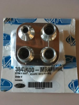
Check this out - I also ordered from vintage air this sweet billet threaded AN fitting bulkhead connector setup to run my firewall lines to. Their part number 384600.

3EA6187E-8E20-4F08-B50F-B4B284B99563.jpeg
 
The guy that was going to help me evacuate and charge the system ended up getting a job out of state. He leaves Friday morning and I'm not ready! The wiring repair could have been done faster if I had been able to work on it straight through.
I do find it interesting how a project gets started and along the way, all sorts of things conspire to make the whole thing take a lot longer than anticipated. I call that "The Snowball effect".
Today I was replacing the ignition switch. The wire plug had melted during the burned wire incident of the other day. I could have soldered and shrink wrapped each wire and used a good plastic plug from another unit but I thought it would be better to replace the whole thing.
In the process, I was able to fix the locking mechanism in the steering column. In 2001 I replaced the original ignition switch when I had a small electrical problem. I messed up something back then and the locking mechanism hasn't worked since then. All 1970 models had the ignition key in the column with a steering wheel lock as well.
 
The snowball effect continues....
The electrical repairs are essentially done but I have decided to do a few more things. The gauges are aftermarket units made by Dakota Digital. When I pulled out the original cluster, I recorded the odometer reading before stowing the old stuff away in the attic. When I programmed the new odometer, I wasn't immediately aware that it has a SIX digit odometer instead of an old style 5 digit. Instead of coding in a 43,000 number, I got a 430,000. The programming allows the owner to make adjustments to the number UP to 100 miles of operation. I discovered my mistake after the 100 miles and now the only way to reset the odometer is to send the brain box to the manufacturer.
DD VHX brain.jpg


It isn't big or heavy so shipping will be cheap. They charge $30 to reset it to either ZERO or whatever number I want. I'm glad that I don't have to send the gauge cluster to South Dakota!
They estimate 7-10 working days to reset it, probably a long estimate. Add in about a week to ship there and back and that puts this project out about another 2 weeks or more.
Not a big deal. I had wanted to reset the odometer for a couple of years now, it has nagged at me that I had it wrong. The "brain" is mounted behind the gauge cluster so since I have it opened up, it does make more sense to do it right now.
The down time does tempt me to do another change...
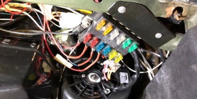
The fuse panel wiring is all back together but I am a bit uneasy about the amount of wires attached to the panel. See the pictures below. The first picture is of my project Charger:
Fuse box XH 1.jpg


Now the next one is of my red car before I swapped to a fuse box with 7 terminals. I have new wires to power the auto dimming rear view mirror with compass and thermometer, the Air Fuel gauge, the aftermarket gauge cluster and the stereo....
Fuse box 2.jpg


I am tempted to tap into the harness and run a separate fuse box to power all NON stock accessories. I may want to add power windows and door locks someday, maybe a better stereo, whatever.
The stack of wires jumped from other terminals makes me nervous. They are all secure but I wonder about stuff moving around during vigorous driving, stuff coming loose or falling on another terminal and causing more melted wires.
 
On my Challenger I have added a Bussman fusebox, it is fed by an 8 gauge wire from the starter relay, half of the box is continuous power, the other half is fed through a relay, terminal 30 (the power supply) is fed from the same 8 ga wire, pin 85 is grounded, 86 is connected to the accessory feed & 87 feeds the other half of the fuse box...

Not the one I have (mine is made by Busman) but similar

https://www.ebay.com/itm/12-Way-Bla...a=0&pg=2047675&_trksid=p2047675.c100005.m1851
 
I had this one out back. Not as fancy though:
A new fuse.jpg
 
Actually it’s very similar to the one I have, accept mine splits the power feed for the two rows of fuses..
 
Now, where to mount it! I'd want to put it either in the trunk or under the hood. At first, I thought the underhood heat would be a problem but my 2007 truck has the massive fuse panel near the battery. The trunk seems like a good idea for the sake of keeping it cooler and dry though, plus it is out of sight.
 
I have mine under the dash since most of the stuff it feeds is in the area of the dash... Keep wire runs shorter...

On my brand Fxxx I have three fuse/relay boxes, engine compartment, forward interior & cargo area..
 
Wheres your battery mounted? Mount it close or use heavier gage wire.
Mine is in the trunk: (Old picture)
Trunk battery.JPG


The reason I am considering a remote mount is because the space under the dash is either cramped or hard to reach with bucket seats, a console and a low mounted Air/Fuel gauge.
 
I made a bracket to mount the auxiliary fuse panel under the dash on the far right side.
Aux FB 1.jpg
AUX FB 3.jpg
 
The glove box will barely clear!
AUX FB 5.jpg

I tapped into the accessory feed on the stock fuse box and used a 10 ga wire. I did decide to just run low current demand accessories from the new panel. The Rear view mirror, the radio, the Air/Fuel gauge and the gauge panel dimmer. The back of the stock fuse panel looks less cluttered.
I didn't think that I had the room under there but once I cut the fuse panel down....
A new fuse.jpg
A 3 XP.jpg


Then made the brackets to mount it, it sits in an easy to reach place that is unlikely to get damaged.

AUX FB 4.jpg

I might wrap tape around the spades near the edge of the bracket....maybe attach terminals on them with the plastic still on the ends?
 
Kern dog nice looking wiring you're doing. What protection do you have going into the new fuse panel. Are you putting a solenoid relay in front of the panel or a master fuse link just curious.
 
Neither. The new panel is just for low demand accessories. The fuses in it are 10, 15 and 20 amps.
The power supply is just a 10 gauge wire about 14 inches long. I can replace it in the future if I add anything that has a current demand higher than what I am using right now. I did this mainly to clean up the clutter with the old panel. I was concerned that the other one had too many jumper wires on the spades and I wanted to get away from that.
 
I would really suggest feeding the new fuse panel from a completely separate circuit... What your doing now just adds more load to the factory wiring... Which was overloaded back in 1970...

I would bring in power straight from either the battery or the alternator, I would feed it through a relay which I would trigger with 12v from your accessories feed..
 
Triggering a fuse panel to only be energized from an accessory feed is the way I have it. I am not sure how to make direct alternator or battery power only work in ACC or run. You mention relays....
Do you mean that the power input goes to the relay, the relay goes to the stock fuse box ACC feed and back to the new panel?
I have just begun to get competent at soldering and shrink wrapping!
 
Auto Transport Service
Back
Top