You are using an out of date browser. It may not display this or other websites correctly.
You should upgrade or use an alternative browser.
You should upgrade or use an alternative browser.
Nicks 426 Whats Missing?
- Thread starter Auggie56
- Start date
- Local time
- 12:58 AM
- Joined
- Feb 20, 2012
- Messages
- 75,274
- Reaction score
- 290,113
- Location
- New Hampster
The filters were a 66 thing. Not sure if those carried into 67 also, but 68-71 didn't have the filters.
Should there be a fuel vapour separator up front after the fuel pump?
Should there be a fuel vapour separator up front after the fuel pump?
It's there. I also looked for the heat shield for the starter and see one. (never seen one before and assume it is correct).
69L48Z27
Well-Known Member
It's thereShould there be a fuel vapour separator up front after the fuel pump?
Looks like we were all wrong. New video and nobody got it.
Almost sure only 66 had filters after tee. Think vapor lock problems.The filters were a 66 thing. Not sure if those carried into 67 also, but 68-71 didn't have the filters.
- Local time
- 1:58 AM
- Joined
- Mar 10, 2010
- Messages
- 32,852
- Reaction score
- 61,153
- Location
- Hanover, Pennslyvania
It's probably a spring clip behind one of the carb linkages that you can't see, F it!
The 1/4" tube that goes from the bottom of the RH exhaust manifold to the air cleaner. Painted orange in this photo...
View attachment 540484
I am going with what RC posted early on. --Nick did -not- address this 1/4" tube --but he did mention the difference with early engines having fuel filters or not.
Maybe no one proposed it?
We will eventually see what Nick tells us is the answer.
Did he start this for fun? Or did he miss something and want us all to share in his missing it?
Either way, I am in with it. I like puzzles.
Last edited:
- Local time
- 1:58 AM
- Joined
- Mar 10, 2010
- Messages
- 32,852
- Reaction score
- 61,153
- Location
- Hanover, Pennslyvania
I am going with what RC posted early on. --Nick did -not- address this 1/4" tube --but he did mention the difference with early engines having fuel filters or not.
Maybe no one proposed it?
Nick specifies 1969 and 1970 and stated he is useing '69 carburetors. (No float bowl vent tubes) Would the orange tube be for those years?
PeteBell68
Well-Known Member
- Local time
- 1:58 AM
- Joined
- Feb 21, 2017
- Messages
- 1,201
- Reaction score
- 1,431
- Location
- Ontario , Canada
I am stumped
- Local time
- 12:58 AM
- Joined
- Feb 20, 2012
- Messages
- 75,274
- Reaction score
- 290,113
- Location
- New Hampster
PeteBell68
Well-Known Member
- Local time
- 1:58 AM
- Joined
- Feb 21, 2017
- Messages
- 1,201
- Reaction score
- 1,431
- Location
- Ontario , Canada
Choke tube?I'm not.
- Local time
- 12:58 AM
- Joined
- Feb 20, 2012
- Messages
- 75,274
- Reaction score
- 290,113
- Location
- New Hampster
correct-a-muundo.
PeteBell68
Well-Known Member
- Local time
- 1:58 AM
- Joined
- Feb 21, 2017
- Messages
- 1,201
- Reaction score
- 1,431
- Location
- Ontario , Canada
Ok gotta ask how did you notice that .I watched both videos the second one twice and looked for a parts diagram on the engine and still didn't see it ,,
- Local time
- 1:58 AM
- Joined
- Mar 10, 2010
- Messages
- 32,852
- Reaction score
- 61,153
- Location
- Hanover, Pennslyvania
Choke tube?
@ 12:45 it's there.
PeteBell68
Well-Known Member
- Local time
- 1:58 AM
- Joined
- Feb 21, 2017
- Messages
- 1,201
- Reaction score
- 1,431
- Location
- Ontario , Canada
I'll watch again but I'm not seeing it . Is it a specific 426 part ?
The 1/4" tube that goes from the bottom of the RH exhaust manifold to the air cleaner. Painted orange in this photo...
View attachment 540484
This has me scratching my head. If the painted tube is connected to the air cleaner and the bottom of the exhaust manifold it is then part of the choke heat system. But in order for air to flow through that loop to move hot air -to- the choke, it would have to be a positive flow -from- the air cleaner. ---Also, my original air cleaner base plate (oval air cleaner) has no connection point for a tube like that.
That brings me back to a question I had long ago. How is the hot air from the manifold expected to get to the choke to heat it? Just float up?? It needs to be pushed somehow. (In my case I am using an electric choke so it is moot for me).
Where is a positive air flow connection for the upper end of that tube??
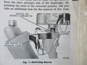
BTW this pic caught my attention from my FSM for 69. It's for anti-icing of the throttle plate of the slant six. The flow direction makes sense. I haven't yet found an illustration/pic of the system in question.

Last edited:
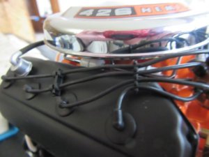
I did find this pic. of both tubes and the sleeve for the tube going to the choke. The tube in question is the one bent with the fitting for the manifold end. The other end goes --where?

@ 12:45 it's there.
I disagree. Only one choke heat tube is on that engine in the video.
Found another pic with both choke heat tubes.
Last edited:
Similar threads
What's it Worth
426 Hemi connecting rods
- Replies
- 0
- Views
- 118
- Replies
- 26
- Views
- 607


