• When you click on links to various merchants on this site and make a purchase, this can result in this site earning a commission. Affiliate programs and affiliations include, but are not limited to, the eBay Partner Network.

Rear shoulder belts in a 1970 Charger

Some people have precision instruments to measure and fabricate unique parts.
Others like me use tape measures, torpedo levels and caveman logic.
Inside the trunk of this car…

IMG_1760.jpeg


The retractors will mount to the back side of the upper rear seat mounting panel. Since it is sloped back for seat comfort and since the retractors Rich and I are working with prefer to be mounted “close to vertical/plumb/upright”, I’m looking at ways to make mounts to reverse the rearward angle of the seat back panel. The goal is to make a platform that is plumb to attach the retractors.
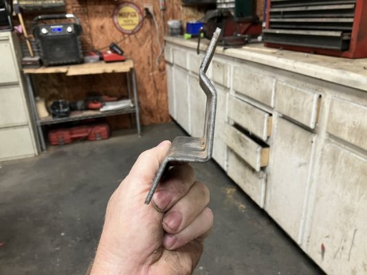
This bracket illustrates the concept…

IMG_2701.jpeg


When viewed at approximately the angle of the seat back panel…

IMG_2702.jpeg

Suddenly there is a vertical mounting point. Inside the trunk looking forward….

IMG_2693.jpeg


Look close, to the upper left you can see the horizontal slit where the belt passes through.

IMG_2694.jpeg


Note the diagonal brace and where it ends near the package tray. Now the right side.

IMG_2695.jpeg


To the upper right is the seat belt slot but look where the diagonal brace ends. THAT is Chrysler build quality in the 60s!

IMG_2696.jpeg


How much of this mis alignment is due to the drive shaft tunnel offset that our cars have? I never noticed this in these cars before.
 
The strange placement of the upper ends of the diagonal bracing means that the left and right brackets will have to be different. Those braces are important, they provide torsional resistance to the roof moving sideways in relation to the lower section of the car. Up front, the windshield in a small way achieves a similar function. I'm wondering if I could trim back the left side a bit like so:

RSB 6.JPG


I could add more welds to the brace to equal the right side...I count 7 spot welds there. If I cut and removed what is above the line, I could add welds below it.
I took a torpedo level (approx 10" long) and held it plumb with the top of it resting on the back side of the trunk/seat back panel. The bottom of the level was approximately 1 1/4" from the panel so I made a quickie cardboard mock up test bracket...

RSB 11.JPG


This will be attached to the trunk divider panel back side, likely welded at the side flanges.

RSB 12.JPG


The side flanges could be drilled and bolts with nylocks could also be used. I wouldn't want this to rattle loose not only for the safety issue but for the rattles as well.

RSB 13.JPG


Knowing I'd need to cut it to fit around the diagonal bracing, I got back into the trunk armed with scissors.

RSB 18.JPG


Right side, I'll trim the cardboard back a bit and test fit....

RSB 21.JPG


It is very hard to lay in a trunk, hold a flimsy piece of cardboard and get a decent picture with one hand...!
Look at the white cardboard piece. Note the distance the top is from the horizontal slot in the package tray where the belt passes through...

RSB 52.jpg


The seat belt sits real close to the edge of the retractor frame so maybe the brackets I'm making need more of a standoff from the trunk divider panel to get the belt in better alignment with the horizontal slot.
 
Last edited:
I might try to crawl into my trunk but the subwoofer is in the way. I just used the flat bracket mine came with and welded several spots to the diagonal brace where it touched.
 
The sloppy placement of the diagonal braces got me thinking. Were other cars as bad?
My red Charger, formally GREEN!

IMG_2726.jpeg


IMG_2727.jpeg


Those look pretty even. Next up, 67 Dart.

IMG_2728.jpeg


IMG_2729.jpeg


Okay, not bad. The Dart did not have slots for shoulder belts though. Now a 72 Duster.

IMG_2732.jpeg


IMG_2734.jpeg


The Duster had shoulder belt slots and the braces were pretty close to even. Finally, a 69 Dart:

IMG_2736.jpeg


The Dart had slots for shoulder belts.

IMG_2738.jpeg


The bracing looks even.
The Jigsaw Charger looks like the braces were installed by a first day apprentice.
 
Just weld in a full cage and install 4 sets of SCHROTH harnesses. :)
 
The non matching angles for the diagonal braces still cracks me up. Was this a Friday car?
Moving on…
This means I can’t just make matching mounting bases for each side. Each will be similar in function but shaped slightly different.
It is obvious that I was not trained in fabrication but I do enjoy it. Starting with the right side, I bent some 16 gauge sheet metal in the vise.

IMG_2767.jpeg


IMG_2766.jpeg


I expected to have to cut the flanges to get them to rest against the flat sections and clear the diagonal brace.

IMG_2769.jpeg


This extension was needed since I want three points of contact for the base mount.

IMG_2773.jpeg


Three self tapping screws just for mock up purposes.

IMG_2774.jpeg


How does it fit?

IMG_2782.jpeg


It lays flat.

IMG_2786.jpeg


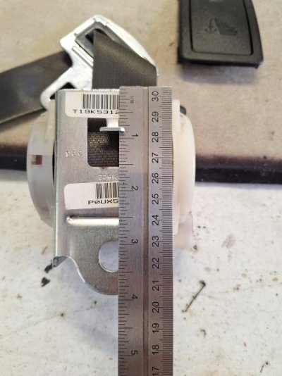
The standoff wil align the belt with the slot which is about an inch in from the edge of the package tray. Rich measured the retractor frames and they are 3 3/4” tall. This base mount is 4 3/4”.
 
That right side mounting base was welded and holes were punched so I can plug weld it to the car.

IMG_2799.JPG


I do need to get the retractors so I can establish the exact mounting position. Rich sent me the measurements so I knew the vertical height these brackets need to be. I'll drill holes and weld a nut on the back side to secure the retractors.

IMG_2800.JPG


IMG_2801.JPG


IMG_2802.JPG


The left side was easy.
The upper corner....

1760937141036.jpeg


Was cut here so the base would fit and clear.

1760937180944.jpeg


It was shaped, welded, holes punched and welds ground down.

RSB 70 D.JPG


The lower right corner lays over the diagonal brace.

RSB 70 C.JPG


RSB 70 B.JPG


The left side will be interesting to weld, I'll be reaching around the mount here and between the wheel tub.

RSB 70 A.JPG


Like with the right side, this still needs the retaining nut welded to the back side. Think of it like the hidden nuts that you screw into to retain the steering box. Of course, I'll weld a thick washer to the back side to reinforce the nut.
 
The mounting face of the retractor has a locating peg with the mounting hole below.

RSB 98.jpg


Rich tested how far the retractor can be out of plumb before the belt won't roll out.
Straight up and down like this, no problem.

RSB 94.jpg


About 10 degrees or so, it was starting to either spin freely or lock.

RSB 97.jpg


I put a torpedo level against the mount as I held it in place and found I was 1/8" out of plumb. That is well within the range of operation.
The plan now is to use the left one as a pattern...

RSB 70 D.JPG


I need to make 2 more for the red car. Rich is making a pair for his Coronet and maybe even the Dart.

10 12 Z1.JPG
 
I had an idea about how to replicate these retractor mounting bases. I thought back to the welding class that Rich and I took earlier this year. Part of the in class instruction was a rudimentary summary of reading blueprints to then cut and shape the metal objects that we would weld together. My years in construction came in handy there so it was familiar.

IMG_2848.jpeg


My rudimentary math shows that the trunk divider panel sits at approximately 13 degrees from plumb. To get the retractors to sit vertical, the mounting bases have to be shaped to accommodate that 13 degrees.

IMG_2849.jpeg


I already test fitted the bases I made in a reverse engineering sort of manner. In short, I worked with the lay of the land and just figured it out. Having done that, I made this pattern (out of a grocery shopping bag) that can be laid over the top of a section of sheet metal to then trace the outline and then be bent to the proper shape.

IMG_2850.jpeg


I took the above pattern and traced it to another piece of paper.

IMG_2852.jpeg


It was folded on the lines and taped together.

IMG_2853.jpeg


The traced pattern was then compared to a LH mount.

IMG_2854.jpeg


It is almost identical dimensionally.

IMG_2855.jpeg


I made it with full length flanges that can be cut back for clearance as needed.

IMG_2856.jpeg


This ought to help speed up the process of making these mounts since it skips past the numerous times I had to climb into and out of the trunk.
The degree of the mount may vary slightly on the model of car, the forward rake of the car too. Still, since @CoronetDarter found that these retractors can still work if tilted a few degrees from vertical/plumb, this ought to work for most people.
One potential issue though….

IMG_2850.jpeg


Making all the bends.
Without a sheet metal brake, you’re limited to bending the metal in a vise or by hand with clamps and hand tools, then tuning up the edges on an anvil or vise.

IMG_2857.jpeg


IMG_2858.jpeg


I’m going to try this now… I suspect that making the multiple bends will be difficult without the versatility of a well engineered sheet metal brake with multiple dies. This would necessitate making the mounts in at least two pieces and then welding them together as I did on the prototypes.
More to come…
 
I can only imagine the complexity of an OEM process to make even a simple mount like this. There is probably a stamping fixture that makes all the bends, right? I’m just some dude in my backyard shop trying to make a few of these for myself.

IMG_2860.jpeg


IMG_2861.jpeg


I have a cheap Harbor freight sheet metal brake, a 6 inch vise and an anvil.

IMG_2862.jpeg


I am no expert at this stuff, like other things that I’m unfamiliar with, I try things and if it doesn’t work, I try something else. It seemed like it made sense to make the innermost bends first.

IMG_2864.jpeg


Since the brake is longer than the bend I have to make in between the outer two….

IMG_2865.jpeg


…. I have to find a way to make the 90 degree bend here.

IMG_2866.jpeg


Again, you can see why the brake won’t help here as the section on the right lifts up to bend the metal.

IMG_2867.jpeg


The die hits as I tried to lever it over.

IMG_2868.jpeg


The mount is 4” wide. A 4” vise would work here but this vise is too wide.

IMG_2870.jpeg
 
Just experimenting…

IMG_2869.jpeg


What if I took a stiff piece of metal like this…

IMG_2871.jpeg


Cut it down to fit inside the outer flanges of the mount…

IMG_2872.jpeg


Used it as a die to pry against…

IMG_2873.jpeg


Clamp the mount vertically…

IMG_2874.jpeg


This got me started but the outer flanges hits the body of the vise.

IMG_2875.jpeg


I finished the bend with the duck bill vise grips.

IMG_2876.jpeg


Then tuned it up on the anvil.

IMG_2877.jpeg


The side flanges are supposed to be 3/4” but what really matters is that the bottom section measures 2 1/16” and the top in 1 1/16”.

IMG_2879.jpeg


With such crude tools, I need to hammer the inside to get a cleaner 90 degree bend.

IMG_2881.jpeg
 
Tuned up, welded, grinder work and it is ready for the final step.

IMG_2887.jpeg


IMG_2888.jpeg


Next to the “prototype”…

IMG_2890.jpeg


I can make several of these with full flanges on 3 sides and trim away what interferes with the bracing in the trunk. The flanges can get the holes punched after I know how much flange is retained.

IMG_2889.jpeg


My caveman fabrication skills actually resulted in the newest mount almost exactly the same size and shape.
This tool works as a flange maker and hole punch.

IMG_2893.jpeg


IMG_2892.jpeg


Air powered… it is a great tool.


IMG_2894.jpeg


Put it in place, pull the trigger for a Ka-chunk!

IMG_2895.jpeg


Now I have a hole to plug weld.

IMG_2896.jpeg
 
Great work. Greg doesn't even have retractors yet, he fabbed the mounting plate face using this photo that I texted him.20251019_145301.jpg
 
Auto Transport Service
Back
Top