• When you click on links to various merchants on this site and make a purchase, this can result in this site earning a commission. Affiliate programs and affiliations include, but are not limited to, the eBay Partner Network.

voltage regulator Question

RonFloyd

Active Member
Local time
12:53 PM
Joined
Jul 31, 2019
Messages
36
Reaction score
73
Location
Putnam County ,Indiana
Hi All ,I have searched and looked through a lot of threads already and have just confused myself so I am wondering if anyone can tell me if this is a constant voltage regulator?
My car stopped charging and it has had the Mopar electronic ignition set installed on it . It is a 65 Coronet with a 68 383 in it . The closest Thing I can find is this P3690732 from Summit . I have went down and picked up a stock unit and it seems to be overcharging on the gauge . I just want to make sure I do not burn the car up by causing an electrical fire , Thank in advance for helping a new to Mopar guy.
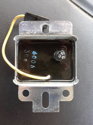
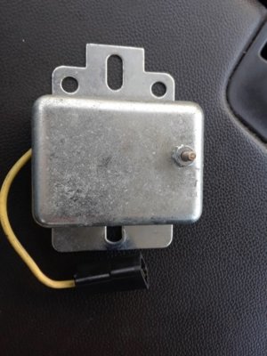
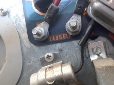
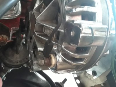
voltage regulator 1.jpeg voltage regulator .jpeg voltage reg add.jpeg
 
I would use a stock type regulator. The aftermarket ones are generally electronic inside a stock looking case. The voltage at the battery when running, should be 14 volts or so. If it is 15 plus then I would check the voltage at the regulator pos. terminal. If it is lower than battery voltage, it will overcharge. Corroded wire and or poor connections can cause this,as well as too much draw on that circuit. I ran my ign. system off a relay to correct an overcharging condition.
 
Ok I have done everything I can think of , The battery voltage at idle is 13.25 and 11.85 at the hot terminal of the VR . All the connections are clean and look good to me . I have tried 3 voltage regulators 2 batteries and 2 alternators. What I am concerned about is the reading on the gauge . It moves up with the RPM's and stays and does not drop down to the middle like it was . At 1500 rpms it is at the mark in between the middle and far right . I am not sure what will fix it . I am about to put a 1 wire GM style on it . I know I can make that work

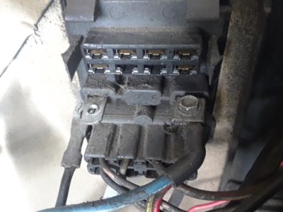
Amp Gauge .jpeg bulkhead .jpeg
 
Search for part# 35-300 on ebay.
It was recommended to me here on fbbo.

Solved all my problems. I have an msd though.

Also, the NAPA electronic flasher not only solved my weak directionals, but made my left dash indicator work correctly.
I did the ammeter bypass too.
 
Thanks for the reply . I will do that , I am curious could it be just a weak gauge? The wires are not getting hot at the firewall and I am lost on electrical side of things . I am going to hook up a volt gauge in the engine bay just to be sure if everything seems ok , if it is I will bypass the amp gauge and hook up the volt gauge inside the car
 
Voltage readings are the best way to tell if your charging system is working properly. 14 to 14.5 volts is perfect. Your 13.5 at idle is still charging, but it might increase with r.p.m. Try turning the lights on etc. And see what the voltage does.
 
Hi All ,I have searched and looked through a lot of threads already and have just confused myself so I am wondering if anyone can tell me if this is a constant voltage regulator?
My car stopped charging and it has had the Mopar electronic ignition set installed on it . It is a 65 Coronet with a 68 383 in it . The closest Thing I can find is this P3690732 from Summit . I have went down and picked up a stock unit and it seems to be overcharging on the gauge . I just want to make sure I do not burn the car up by causing an electrical fire , Thank in advance for helping a new to Mopar guy.
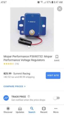
View attachment 823671 View attachment 823672 View attachment 823673
What type of alternator are you using? All origional vehicles up up to model year 1969 used a single wire field circuit with one brush insulated and the second brush grouded. The original regulator was a mechanical device that applied EITHER 12 volts to the alternators field for maximum output or 7-9 volts for less thsn maximum output or 0 volts for no output. The voltage regulator was constantly operating between those parameters to provide an average alternator output voltage of 14 volts (nominal). Output CURRECT was controlled by design or impedance of the diodes and stator windings.
Begining with the 1970 model year, an electronic voltage regulator was introduced along with a isolated field alternator (both brushes were insulated). The alternator's field voltage was controlled by the regulator's internal circuit (transistors) tuning on/off to produce an average alternator output voltage of 14 volts without any moving parts. Again, output current was design controlled by the diodes and stator windings. A superior system compared to the origional mechanical control.
Later, manufacturers came up with an electronic replacement for the mechanical regulator which works quite well and allows the use of the origional alternator design (1 insulated brush 1 grounded brush). Field voltage is switched ectronically.
The square back alternator uses a different diode arrangement but the same isolated field design as previous units. As I said before: WHAT ALTERNATOR ARE YOU USING? That will make the determination as to what regulator to use. Powermaster systems NOT included as their operstion is similar to GMs 10SI 12SI units with the regulator internal to the unit. Just my opinion of course.
Bob Renton
 
All the paperwork says is chrome square back on the paperwork I have . Sorry It doesn't give voltage

View attachment 826225
Ron,
It is difficult to see the field (brush connections) ftom your pix. All the alternators are rated at 12 volts; maximum AMPERAGE can be as high as 60 amps (@ 12 volts). There is a stamping pad which shows the part number, original build date, amp and voltage rating. Do not confuse these stamped information marks with the casting date information. USUALLY this pad is near the output stud on a fairly large flat surface. It appears that your is a standard square back alternator that was disassembled, chromed and rebuilt.
It appears that the output connection is the heavy black wire directly above the white plastic insulated washer. Cannot see the brush connection directly behind the heavy black wire. I cannot tell if there is anything connected to it or not or if it has been intentionally grounded.
A lot depends on if your original wiring has been modified (by others) to accommodate an isolated field alternator or not. Better pixes would be nice especially of the alternator and the regulator wires. If its a true isolated field alternator, both brushes should be insulated and have a single wire (one blue and one green wire) connected to each brush... need a little more information....
Bob Renton
 
If it’s an aftermarket “high powered” head unit, the memory lead also supplies the main current to the on-board amp. Really needs to be on the alternator side of the ammeter, otherwise you will see that current draw on your ammeter as charging.


In one of pics above, shows the early style bulkhead connector. Looks like one of the screw type charge circuit leads is missing, has it been rerouted?
This is a '62, anything like yours? Could have changed by '65
20150806_120130-jpg.jpg
 
Last edited:
Ron,
The bulkhead connector on my RS23V0A******* GTX looks nothing like what you show. All of my bulkhead connectors plug into the fitting, including the fusable link that protects the alternator output circuit.
I presently use an origional 1970 vintage Mopar round back alternator, rated at 37 amps at 12 volts. I've changed all the diodes to 60 amp units and the 60 amp stator (green colored windings) and the origional rotor assembly, installed all new bearings and brushes and holders. It provides all the amps my car needs. My GTX is an origional almost numbers matching car....with a few engine internal mods. I never intend to upgrade to a high wattage "make your ears bleed" stereo system....it still has the origional working AM only radio.
Has your origional wiring been "modified" ?? Its difficult to follow someone elses work without a diagram....too many "experts".....
Bob Renton
 
The wiring has not been modified . That's one of the best things I have found so far . the stereo is a pioneer CD player not really a high output unit . But it was all tied in through the fuse box . I have found a local guy who is a lifelong Mopar guy that is willing to come out and look and show me what I am missing . He has a garage full of the Old mopars from a 49 with a 392 hemi in it to 71 demon's I do appreciate all you guy's helping and trying to lead this dummy in the right direction. I will learn this stuff , Thank you again
 
Ron,
IF the alternator shown in your pix is a square back unit, it REQUIRES an electronic regulator and both brushes to be connected OR if your regulator is a mechanical type or an electronic replacement regulator, then one of the two brushes must be grounded (does not matter which one is grounded) to operate properly. All the regulator does is to vary the alternator's rotating field voltage to limit the output. When working on the charging system, be careful not to short circuit or unintentionally gtound anything. Disconnect the battery's negative terminal b4 proceeding.
Bob Renton

Thank you . I Borrowed a stock alternator off a 66 put on a stock regulator and everything is working great . Just got home from a 120 mile drive today. Thank you very much for everything .I ordered a stock type alternator to put on will be here tomorrow. Again thank you for everything
 
Auto Transport Service
Back
Top