• When you click on links to various merchants on this site and make a purchase, this can result in this site earning a commission. Affiliate programs and affiliations include, but are not limited to, the eBay Partner Network.

WIRING HELP please assist 383 1971 charger adding MSD

Rikker

FBBO Gold Member
FBBO Gold Member
Local time
12:25 AM
Joined
Dec 30, 2016
Messages
86
Reaction score
21
Location
california
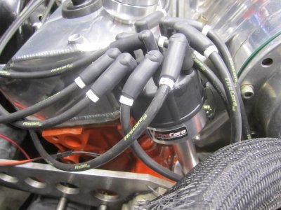
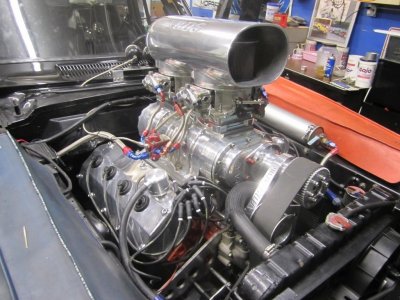
I have a 1971 dodge Charger SE 383. I am converting to MSD plug in play (part#8386). I have checked the forum and could not find the exact answer. Also the wiring diagrams I found on line are slightly different than mine. MY question is the MSD 8386 does not use a ballast, or ignition module. (See attached MSD installation pic). Has anyone put a MSD 8386 on a 1971 charger 383 or similar. Also my old wiring might be jacked?(see below ?'s and pic)
thumb_IMG_2218_1024.jpg


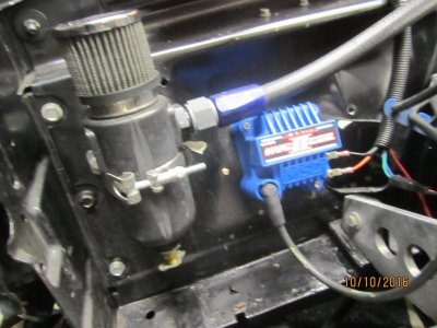
Here is my current wiring(See attached)
Starting on the orange ignition module on the left side at 10 O'clock position is a brown/white stripe wire that went to my black wire on my old distributor(stock), at 8 O'clock is a white/ black stripe wire that went to the white lead on the stock distributor. FIRST Question(1)-What do I do do with these two wires? At the 6 o'clock position is a gray/yellow wire that goes to the left side of the ballast which is tied into the alternator wire. At the 4 o'clock position is a black/yellow which went to the negative side of the old coil.Second(2) question is this the ground and does this now go to the new ground(black) pigtail to new MSD coil? At the 2 o'clock position is a green/red stripe- that went no where. THRIRD(3) where does that go?

Moving to the right side of the ballast is a brown wire that went to the positive side of my old coil. Fourth(4) question is this the power that now goes to the positive+ side of the new coil. Fifth(5) question there was also a brown wire from the bottom of the fuse block that went to the negative-side of the old coil. IS that the tach wire and should that now go to the Gray tach input lead to the new distributor? Then last question -Unplug the leads going to the ballast correct? Thank you in advanced!
thumb_IMG_2217_1024.jpg
 
The red wire coming odd the key switch can be the positive to the coil.Make sure it the one that stays on in the crank position.There are 2 wires now coming from the key switch to the ballast.One is hot in the start position and the other is hot when key is in the run position.You can also connect those 2 wires to feed the coil.
 
In my pic there is a brown wire coming from the fuse block to the right side of the ballast in the pic. IS this what you are referring to when you are talking about the red wires I can connect together then to the coil?
 
My pic of my current wiring and questions are below the MSD installation pic. I hope both pics were uploaded.
 
You will need a hand,check the wires with a test light.Key & run positons to find the wire to use.Also make sure the wire itself is still in good shape,if not install a new wire after you determine which one:thumbsup:
 
Planning to install the same system with my factory tech. I was wondering if you connected the tech and how accurate is your tech with MSD system?
 
Thank you , Copy will test for hot. After finding the hot lead what do I do with the wires coming off the ignition module.- Could you see if you could have any input on the 5 questions I have in the first post that are after/under the MSD installation pic.
 
Planning to install the same system with my factory tech. I was wondering if you connected the tech and how accurate is your tech with MSD system?
I will let you know about the tach after I get it installed, just trying to figure out my wiring, hopefully i can figure it out
 
I have a 1971 dodge Charger SE 383. I am converting to MSD plug in play (part#8386). I have checked the forum and could not find the exact answer. Also the wiring diagrams I found on line are slightly different than mine. MY question is the MSD 8386 does not use a ballast, or ignition module. (See attached MSD installation pic). Has anyone put a MSD 8386 on a 1971 charger 383 or similar. Also my old wiring might be jacked?(see below ?'s and pic)View attachment 414401

Here is my current wiring(See attached)
Starting on the orange ignition module on the left side at 10 O'clock position is a brown/white stripe wire that went to my black wire on my old distributor(stock), at 8 O'clock is a white/ black stripe wire that went to the white lead on the stock distributor. FIRST Question(1)-What do I do do with these two wires? At the 6 o'clock position is a gray/yellow wire that goes to the left side of the ballast which is tied into the alternator wire. At the 4 o'clock position is a black/yellow which went to the negative side of the old coil.Second(2) question is this the ground and does this now go to the new ground(black) pigtail to new MSD coil? At the 2 o'clock position is a green/red stripe- that went no where. THRIRD(3) where does that go?

Moving to the right side of the ballast is a brown wire that went to the positive side of my old coil. Fourth(4) question is this the power that now goes to the positive+ side of the new coil. Fifth(5) question there was also a brown wire from the bottom of the fuse block that went to the negative-side of the old coil. IS that the tach wire and should that now go to the Gray tach input lead to the new distributor? Then last question -Unplug the leads going to the ballast correct? Thank you in advanced!
View attachment 414402

This is a very simple installation that really requires the removal of all the previous junk ( electronic box and ballast resistor) for a nice clean look. If you must, you can leave the ballast hanging there for nostalgic reasons. Remove the original electronic ignition box and all wires going to it - none are necessary. Starting at the ballast resistor, join the two wires that would originally feed it to a matched (original) colored wire run straight to the positive terminal on the coil. That's your ignition feed and will supply 12V+ to the coil in both START and RUN position of the ignition switch. Regarding the coil, I would use the electronic version as opposed to the can style but if you stick with the can make sure it does not need a ballast resistor to operate properly. Information about the coils can be found at MSD's site. I use the electronic version due to it's higher output, smaller size and compatibility with capacitive discharge style distributors. The tack hooks up like any tack would when there's a coil present, but MSD has already given you a grey feed wire to attach to. If you are confused you can always connect your tach directly to the negative coil terminal. If you are going to remove the ballast resistor completely this would be an ideal time to mount an ignition relay in it's place for future electrical upgrades and prevent overloading the ignition system.
 
This is a very simple installation that really requires the removal of all the previous junk ( electronic box and ballast resistor) for a nice clean look. If you must, you can leave the ballast hanging there for nostalgic reasons. Remove the original electronic ignition box and all wires going to it - none are necessary. Starting at the ballast resistor, join the two wires that would originally feed it to a matched (original) colored wire run straight to the positive terminal on the coil. That's your ignition feed and will supply 12V+ to the coil in both START and RUN position of the ignition switch. Regarding the coil, I would use the electronic version as opposed to the can style but if you stick with the can make sure it does not need a ballast resistor to operate properly. Information about the coils can be found at MSD's site. I use the electronic version due to it's higher output, smaller size and compatibility with capacitive discharge style distributors. The tack hooks up like any tack would when there's a coil present, but MSD has already given you a grey feed wire to attach to. If you are confused you can always connect your tach directly to the negative coil terminal. If you are going to remove the ballast resistor completely this would be an ideal time to mount an ignition relay in it's place for future electrical upgrades and prevent overloading the ignition system.

Thank you very much! I too have the electronic coil which does not require the ballast. The only question I have left is regarding the ballast. On the left side there is a feed that connected to the ignition module that I will eliminate, but then there is a jumper wire to one of the Alternator wire as well. Can I eliminate that feed to the alternator wire as well? Thank you again!
 
This is a very simple installation that really requires the removal of all the previous junk ( electronic box and ballast resistor) for a nice clean look. If you must, you can leave the ballast hanging there for nostalgic reasons. Remove the original electronic ignition box and all wires going to it - none are necessary. Starting at the ballast resistor, join the two wires that would originally feed it to a matched (original) colored wire run straight to the positive terminal on the coil. That's your ignition feed and will supply 12V+ to the coil in both START and RUN position of the ignition switch. Regarding the coil, I would use the electronic version as opposed to the can style but if you stick with the can make sure it does not need a ballast resistor to operate properly. Information about the coils can be found at MSD's site. I use the electronic version due to it's higher output, smaller size and compatibility with capacitive discharge style distributors. The tack hooks up like any tack would when there's a coil present, but MSD has already given you a grey feed wire to attach to. If you are confused you can always connect your tach directly to the negative coil terminal. If you are going to remove the ballast resistor completely this would be an ideal time to mount an ignition relay in it's place for future electrical upgrades and prevent overloading the ignition system.
Disregard the last question I would imagine that jumper fed the power to the ignition module so that it not needed any more. Thank you again.
 
For othlers that might want the next step in igition,the MSD 6al-2 ignition box is programmable with a laptop and you can lock out the distributor because it will now be managed by the ignition box.You can use a stock electronic distributor or the Firecore or MSD ditributor

5.13.15 003.jpg 5.13.15 005.jpg 10.10.16 009.jpg
 
on a quick view...

you don't need to remove ballast or cut and splice any related wire. Use the existant coil wire which is still attached at ballast ( and spliced from there to the ign switch ) and you can keep ballast on firewall simply using a jumper between both ballast leads... OOOOR remove the resistor from the back groove of ceramic and sold a jumper in it... will keep stock look if you care.

HOWEVER, your wiring looks so hacked up, ( due the later ECU install ) that you can make a full new harness to install the new ign system... and refresh the rest of the wiring harness.

Remove ALL the wires related to the Mopar orange ECU. No one will be used. That module and related wires was added anyway since they didn't exist back in 71. This will clean up the harness too.

Alt wires has nothing to do with ign system. keep them just like it is.

Existant tach wire to - lead of coil needs to be wired to the new tach provision on new dist

Ground dist provision can be sourced anywhere you want. You can use the dist clamp bolt for that... or the coil bracket bolts ( if you still have the coil on stock location )
 
Last edited:
( the green traced red wire at 2 o'clock goes anywhere on 4 pins module with 2 prngs ballast... is only used on the aux resistor for 4 prongs ballast and 5 pins ECU modules. Harness is simply built like that with the green wire to be used on either ECU setup if needed )
 
( the green traced red wire at 2 o'clock goes anywhere on 4 pins module with 2 prngs ballast... is only used on the aux resistor for 4 prongs ballast and 5 pins ECU modules. Harness is simply built like that with the green wire to be used on either ECU setup if needed )
Very helpful thank you for the advice and knowledge.
 
Hi all,

Just digging up this thread instead of creating a new one.

An MSD ingnition package has been installed now on my '69 Coronet (440) and the tach is not hooked up.
The distributer (MSD partnumber 8387) does provide the gray wire for a rpm signal.
It is combined with a MSD Blaster SS coil (part number 8207).
It states in the MSD manual this provides a 12V signal for the rpm meter. (positive? +, negative? -)
Originally the signal wire for the tach is hooked up the the negative pole on the coil.
Can i just hook this up?
As per Chrysler schematics, there are 2 wires for the tach, 1 wire from the coil negative terminal and the other appears to be a fused 12V.

I assume 2 positive feeds into a rpm gauge will burn something or is it supposed to be like this?
Or do i need to start to do a better job on electrical study? :)
 
Auto Transport Service
Back
Top