You are using an out of date browser. It may not display this or other websites correctly.
You should upgrade or use an alternative browser.
You should upgrade or use an alternative browser.
Adjustable Proportioning Valve Mounting HELP!
- Thread starter 1968rt
- Start date
MIKESPOLARA
Well-Known Member
Is it Ok to mount before the distribution block? I was told it could set off the warning light when the pressure is decreased.
View attachment 1221875
You have it plumbed to the rear line, as long as that line remains feeding the rear brakes up to and after the dist block you are fine
Is it already adjusted? If it's adjusted and low pressure valve did not activate then it's good, once adjusted it doesn't change unless you re-adjust
if it is for the rear brakes, it should be after the distribution block.
That is where you want it. You do not want it between the master and valve as shown in your photo.
gkent
Well-Known Member
According to Rick Ehrenberg all that distribution block **** can be discarded. Plumb the rear brakes directly to the proper master cylinder reservoir using a Y on the rear end. Plump the fronts directly to the appropriate rusing a T. Plump the prop valve anywhere in the rear line. In its current state, the brake warning light will only come on when you have no brakes - presumeably you won't need a light to tell you that !!
- Local time
- 4:12 PM
- Joined
- Feb 22, 2021
- Messages
- 3,536
- Reaction score
- 7,402
- Location
- Roswell, New Mexico
That's how mine is done. No distribution block,According to Rick Ehrenberg all that distribution block **** can be discarded. Plumb the rear brakes directly to the proper master cylinder reservoir using a Y on the rear end. Plump the fronts directly to the appropriate rusing a T. Plump the prop valve anywhere in the rear line. In its current state, the brake warning light will only come on when you have no brakes - presumeably you won't need a light to tell you that !!
proportioning valve plumbed to the rear. Also
have a 2lb residual check valve in each line.
Dual diaphragm booster, 1.032 Dia master.
Ford dual piston calipers on the front, Ford
Explorer single piston on the rear. Pedal feel is
excellent. Stops on the proverbial dime.
gkent
Well-Known Member
Get rid of the residual check valves - not required with disc and were only needed on old style drum cylinders.
- Local time
- 4:12 PM
- Joined
- Feb 22, 2021
- Messages
- 3,536
- Reaction score
- 7,402
- Location
- Roswell, New Mexico
They're needed in my case due to rhe pistonGet rid of the residual check valves - not required with disc and were only needed on old style drum cylinders.
retracting a little further into the caliper
with no pedal pressure. The OP won't know
if they're needed until he gets his system
installed.
The valves keep the fluid in the calipers from siphoning back into the master cylinder when you let up on the brakes. If your master cylinder isn't that low or is slightly above the calipers, it can still happen if you're parked on a hill!
If you ever have to press on the brake pedal twice to get a hard pedal, you need them.
Last edited:
Red63440
Well-Known Member
That is where you want it. You do not want it between the master and valve as shown in your photo.
I will ask why it has to be mounted after the block? I am doing a front disk conversion on my 64 Fury. It has a updated dual master cylinder distribution block with no proportioning valve and I will be using the adjustable valve for the rear brakes. The distribution block is mounted on the frame rail in its original position.
Didn’t mean to step on your post but it seems silly to start another to ask one question.
You want it past any proportioning or distribution points. Once there it can do its job correctly as far as adjustable pressure control to the two rear brakes.I will ask why it has to be mounted after the block? I am doing a front disk conversion on my 64 Fury. It has a updated dual master cylinder distribution block with no proportioning valve and I will be using the adjustable valve for the rear brakes. The distribution block is mounted on the frame rail in its original position.
Didn’t mean to step on your post but it seems silly to start another to ask one question.
So the adjustable valve goes between the block and the rear flex hose.It’s a 64 Fury, there is no valve in the brake line and just a solid brass dual port block that changes the direction of the fluid.
Red63440
Well-Known Member
Thanks for your response and I respect your knowledge but you still haven’t given a mechanical reason why it can’t be done. Later cars had the distribution blocks on the inner fender well which made it easy to do what you recommend but I won’t mount a valve that can be damaged outside a protected area. Thanks again!
All I can tell you is what I was always told and have done. The adjustable valve goes after any proportioning or distribution points. Without seeing your cars brake configuration it is hard to tell you anything else. The valve is a control. You want it set up so the pressure you are trying to control inputs the valve. The output goes directly to what you are trying to control. So on the valves output you do not want the fluid going anywhere else. You want it going to the rear wheels in your case.Thanks for your response and I respect your knowledge but you still haven’t given a mechanical reason why it can’t be done. Later cars had the distribution blocks on the inner fender well which made it easy to do what you recommend but I won’t mount a valve that can be damaged outside a protected area. Thanks again!
Red63440
Well-Known Member
I understand that, the 64’s had a very simple system when built. I changed to a dual master cylinder and due to that I went to a 64 style distribution block which as far as hydraulics go is nothing more than a block that redirects the fluid but it does not limit or share the fluid. The front port on the MC goes to the rear inlet on the distribution block, makes a 90 degree turn and goes directly to the rear brakes.
The rear port on the MC goes to the front inlet on the distribution block and is split left and right to the front brakes. There is nothing that meters the pressure or flow of the hydraulic fluid after it leaves the MC.
Hope this helps you to understand the system in my car.
The rear port on the MC goes to the front inlet on the distribution block and is split left and right to the front brakes. There is nothing that meters the pressure or flow of the hydraulic fluid after it leaves the MC.
Hope this helps you to understand the system in my car.
Last edited:
gkent
Well-Known Member
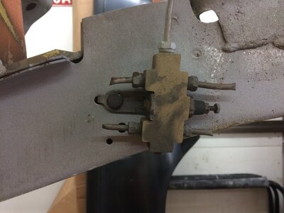
Below is the forward most block (first photo).
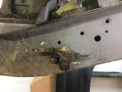
Both front and rear lines from the m/c go in the front of the block. The top rear line and top line go to each front brake. The bottom rear line goes to the rear brake block (2nd photo).
The ONLY purpose this block serves is to measure any pressure difference between either the front or rear lines (indicating a low fluid level in a reservoir) and if so, turn on the "brakes" light.
NOTE: I may be mistaken on the entry/exit points but that doesn't matter - the point is this block is useless and can be sold for scrap.
The block in the second photo is the factory preset proportioning valve.
BOTH of these can be tossed in the trash. Run your front line to a T block from which you feed each caliper.
Put your adjustable prop valve anywhere you damn well please as long as its before the rear brake splitter.
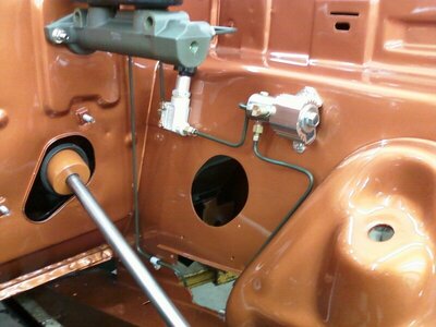
The last photo is probably one of the cleanest installs I've ever seen.


gkent
Well-Known Member
64’s DO NOT have a proportioning valve
So what !! They didn't have dual reservoir master cylinders either ... until you installed one! Get rid of that useless block you have.
Last edited:
Red63440
Well-Known Member
Maybe this will help….
C-body Polara, Coronet, Fury, Belvedere, Valiant, Barracuda, Satellite brake line distribution block for dual master cylinder cars
When converting to dual master cylinder or disc brakes. This is a brand new distribution block for 62-64 cars. This block is made exactly like the original but separates the front brakes from the rears, so if a line was ever to blow out you would not loose both front and rear brakes. The block mounts to the frame just below the master cylinder just like the original. The master cylinder lines screw into the top while the left and right front lines screw into the sides and the front to rear screws into the back. This block is for dual master cylinder upgrades. With safety as the number one concern with brakes this is a simple upgrade to make you car safer. If you are converting to a dual master cylinder simply attach the block plumb new master cylinder lines and you are done. If you are converting to disc brakes do the same but remember to add in your adjustable valve somewhere in the front to rear brake line so you can tune in the rear brakes. This piece is exact to NOS in every detail. It is the correct size, shape and thickness brass with the bracket attached exactly as the original was. This is a concourse level brass part with phosphate bracket. The original is impossible to restore since the bracket does not come off the piece. Please view my other brake listings.
Similar threads
- Replies
- 8
- Views
- 991
- Replies
- 1
- Views
- 1K
- Replies
- 22
- Views
- 2K


