• When you click on links to various merchants on this site and make a purchase, this can result in this site earning a commission. Affiliate programs and affiliations include, but are not limited to, the eBay Partner Network.

I'm getting close to switching to a roller cam in the big block!

Since I've never installed a roller cam in an engine that wasn't built with one, I still wonder about how all this will work.
The concept of the back side of the camshaft sprocket riding against the block seems weird even with a Torrington bearing. I haven't looked into how the cam button is modified for the required fore/aft limits of the camshaft. The limit that I read was .010 of an inch fore/aft. That confuses me, since the lobes in a roller cam are not tapered, the roller wheels on the lifters seem like they'd be fine with the wheel hanging off the edges a little. I'm just curious as to why they are supposed to restrict the fore/aft movement so much.
Back to the clearancing of the cam button....
I may buy a reinforced timing cover or weld a plate over mine. That makes sense.
Regarding the cam thrust button....
Let me guess....You must first measure the depth of the timing cover and gasket, then measure how far out the cam button sits out from the face of the block.....then somehow mill down the cam button to get to a number that is less than the depth of the timing cover by no more than .010.
I'm supposed to use a straightedge and plane across a tiny cam button to the face of the block? How is that done with accuracy?
Two things I can think of for the fore/aft movement limits of travel.
1. Any fore/aft movements will induce sliding instead of rolling of the lifter wheel.
2. Stress on the oil pump/dizzy drive gear.

When I did my motor I used one of the roller style cam buttons.
https://www.jegs.com/i/COMP-Cams/24...MIg-etpvjrjQMVUgKtBh2L4BwYEAQYASABEgId7_D_BwE
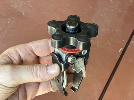
Thank you.
What did you do to get to the desired thrust clearance number? Did you have to mill away some material ?
 
Thank you.
What did you do to get to the desired thrust clearance number? Did you have to mill away some material ?
I have an aftermarket timing chain cover as well as a thrust washer between the camshaft gear and the block. I had a local machine shop measure the thrust washer and remove that exact amount from the back of the camshaft gear. I don't remember it being much, maybe like .015-.020?
I also have an aftermarket timing cover so once the camshaft gear was machined I assembled everything as if I was putting it together for the final time and measured for camshaft thrust clearance towards the timing cover. I did not have to add shims or remove any material as the clearance was good.
 
When using a stock timing cover and the Comp 204 rollerized button……..this is how I do it:

The button is too long to fit under the stock cover, so I take two sockets(big one on the outside, about 3/8” bigger than the button on the inside), and hammer a “dimple” into the cover.
Adjust as necessary for desired thrust clearance.

Some aftermarket covers will clear the 204 button.

IMG_3916.jpeg


IMG_3917.jpeg
 
That is hilarious. Look at the timing chain cover in this pic.

Short block 1.JPG
 
When using a stock timing cover and the Comp 204 rollerized button……..this is how I do it:

The button is too long to fit under the stock cover, so I take two sockets(big one on the outside, about 3/8” bigger than the button on the inside), and hammer a “dimple” into the cover.
Adjust as necessary for desired thrust clearance.

Some aftermarket covers will clear the 204 button.

View attachment 1882689

View attachment 1882690
Sometimes when I’m doing something new, it is the unknown that makes me nervous. If this would allow me to retain the existing cover that would be great. I take it the dimple in the cover means it won’t need any additional reinforcement?
 
I take it the dimple in the cover means it won’t need any additional reinforcement?

I like to set it up so the cover is just about touching the W/P housing……..so, whatever it takes to end up with that.
 
I have to change the valvesprings.
The thought of changing 16 valve springs along with checking installed height with every one of them seems really time consuming.
What methods do you use to get this done? Years ago, I changed the valve stem seals on this engine with the heads in place using compressed air to hold the valves in place and a hand held twisty tool to compress the springs to remove and reinstall.
Is that the only way to do this job with the heads in place?
One of the reasons that I considered Trick Flow heads was to simply swap heads rather than to change every spring.
Please don't think I'm complaining....I'm just curious if it makes more sense to pull these heads and change the springs on the work bench.
 
The thought of changing 16 valve springs along with checking installed height with every one of them seems really time consuming.
There is really no reason to check installed height on every valve. The heads should be pretty consistent, and unless you are on the hairy edge with respect to lift, just check one set on each head. If they are reasonably consistent then you are good to go.

Years ago, I changed the valve stem seals on this engine with the heads in place using compressed air to hold the valves in place and a hand held twisty tool to compress the springs to remove and reinstall.
Is that the only way to do this job with the heads in place?
One of the reasons that I considered Trick Flow heads was to simply swap heads rather than to change every spring.
Please don't think I'm complaining....I'm just curious if it makes more sense to pull these heads and change the springs on the work bench.
Using the individual spring compressor with compressed air to hold the valves really doesn't take too long once you get going. You would spend a lot more time pulling heads and would need to replace the head gasket as well.
 
There is really no reason to check installed height on every valve. The heads should be pretty consistent, and unless you are on the hairy edge with respect to lift, just check one set on each head. If they are reasonably consistent then you are good to go.


Using the individual spring compressor with compressed air to hold the valves really doesn't take too long once you get going. You would spend a lot more time pulling heads and would need to replace the head gasket as well.

unless you ate twisting to nearly valve float on every gear change ......
 
I made something like that that didn't work that well. I'd be inclined to buy one this time.
Thank you.
 
Kern:

Checking installed height gives you the ability to measure what your closed pressure is. From there you can measure open pressure based on your cam and verify it is what you need.

But an important measurement is also to measure from the bottom of the retainer to the valve guide oil seal. This measurement must be larger than the lift on your cam. It usually is, but bad things happen if your lift is higher.
You also want to check for coil bind of the inner and outer springs. Easily done in the spring pressure checker, you just need to account for the step on the retainer that affects the height of the inner spring. I use a washer that is the same thickness as the retainer step.
 
I’ve done quite a few on the car spring installs. Everyone gets measured and adjusted +/- .005” using a combo of .015”, .030”, and if necessary.060”. Make sure you have a selection of the correct shims that fit your guide diameter. Make sure the retainers are correct for the new springs. Make sure the locks fit both the retainer and the valve type/diameter. The Comp style tool works well using a small magnet, and a sharp pic if needed to pop the keepers apart. Remove rocker assemblys and all spark plugs. Rap each retainer solidly with a soft face hammer to loosen the locks. Bolt up the tool first. Air up the cylinder. Have the pic and the magnet setting on your fender cover. Depress the retainer being careful to center the tool right to left. If it’s not centered start over. Depress the retainer and put the pic between the keepers to split them apart. Grab the loose one with the magnet. Then grab the second one. Do not release the tool until both keepers are removed. Uses a height mic to measure the installed height. Add shims and recheck. Shoot for a height. Example 1.880” using the mentioned shims you will be able to shim to either 1.875”, 1.880”, or 1.885”. Place the retainer on the spring well centered, then compress. Install one keeper on the inner (intake manifold) side of the valve. I use my fingers. You will have the retainer well collapsed. Release tension slightly until the retainer slides over this keeper. Now install the other keeper on the outer side of the head. Do not release the tool with only one keeper installed. If the first keeper is in the wrong spot? Grab the magnet, remove and start over. Once both valves are done. Rap the retainer to assure proper seating. Then move to the next cylinder. You won’t have to deal with 330# on the seat like I do. Just did 220# on the seat for a customer. Pretty easy.
Doug
 
Auto Transport Service
Back
Top