• When you click on links to various merchants on this site and make a purchase, this can result in this site earning a commission. Affiliate programs and affiliations include, but are not limited to, the eBay Partner Network.

Making the HEI conversion SUPER simple!

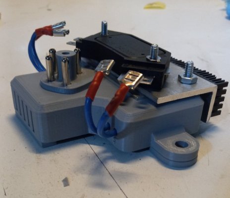
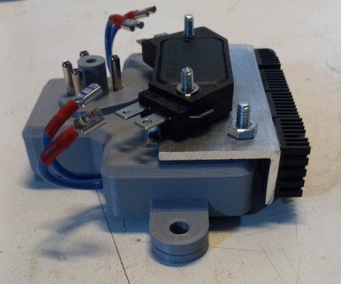
I saw those adapters when I first started to research the conversion. I just didn't like the idea of adding new wires or cutting the OEM ones. The reason I made my mount was to try and make the swap plug and play. Other guys has done this by gutting an old mopar ECU.

You can even add a relay to the system quite easy as well . Basically just substitute it for the OEM Ballast resistor. Use the IGN 1,2 wire for the trigger, terminal on the relay. The other 2 wires from the ballast which power the ECU and Coil are connected and output power of the relay. Add your input power ( usually from alternator stud ) and finally ground terminal of the relay. Still keeps factory harness installed.

OR just bypass the relay if you think your factory wiring is up to the task.

Im still playing with my mount trying to perfect it. Those little HEI module create alot of heat ! . As another member wrote in his own thread , my original design was lacking enough heat sink. His solution was the AC delco heat sink ADDED to mine which has been working great from my understanding.
 
An ign relay is a good idea. I have had them on all my cars. HEI is an inductive system; reducing voltage drop provides more energy to the coil & module.
 
UPADATE:

For any that have been flowing this and other threads in this forum about that HEI conversions. I have modified my original design slightly to ensure that the module is kept at an acceptable temperature.

Modifications

1. More venting was added to allow for air to completely past threw the entire mount. This will aid in actual "air flow" where there is actually a path for air movement from one end of the mount to the other.

2. Doubled up on aluminum plates . There is now 1/4" of aluminum plate

3. Added additional heat sinks to the backside of the mount. With the added venting this will allow for quick heat dissipation.

Keep in mind, if the correct parts are not installed it doesn't matter how big your heat sink is, you will cook your module. Another member here @zombezoo has an excellent thread that went threw some problem solving of the HEI setup. It also point out how important it is to have the correct ignition coil for the setup !!

ENjoy!

This is a great idea.
As per the rules here, we can't advertise the sale of such things outside of the sales section of the forum but I am interested. I'll check in with you through PMs.
I have a 1.6 ohm coil in one car, a 1.8 ohm coil in another. Are they compatible with the HEI system?
 
Yes, those coils will work.....but.......if they were designed to be used with a bal res, then the bal res should be used.
For the purposes of just generating a spark, elec ign whether it is Chrys, Pert, HEI or some other......it should just be viewed as an electronic switch that replaces the mechanical function that the points did.
 
^^^^This is misleading, the module itself requires full voltage and can not be fed through the resistor. Mine runs at 14+ volts typically.
 
^^^^This is misleading, the module itself requires full voltage and can not be fed through the resistor. Mine runs at 14+ volts typically.

If you were to run the factory wires of a 2 post ballast resistor . The wire that goes to the Mopar ecu is full battery in run. You would use this same wire for your HEI module . The coil wire is what sees the resistance of thr ballast not the ECU / module

THIS IS NOT TRUE for a 4 post ballast. These style reduce current to both the coil and ecu
 
Not trying to start an argument, just pointing out that it needs to be wired correctly. Carry on.
 
Wrong, RJ Squirrel. The module gets the FULL 12 volts, but when using a coil that needs a bal res, the res is used with the coil [ not the module ]. Post #24. I 'm sure somebody will post a diagram...
 
Wrong, RJ Squirrel. The module gets the FULL 12 volts, but when using a coil that needs a bal res, the res is used with the coil [ not the module ]. Post #24. I 'm sure somebody will post a diagram...
Here you go:
Mike
 

Attachments

  • IMG.pdf
    411.4 KB · Views: 23
This little project has become a little obsession of mine. And have made some major updates to my design

My original design lacked enough heat sink, as discussed. Other members had found that adding an AC Delco heat sink to my design was enough to solve the problem and most would be happy with that.

I gave myself a high school lesson on heat absorption and dissipation and went at improving my setup.

What I learned is that for constant heat disappation, you want to have as much surface area as possible. My previous attempt at simply adding mass to the design was not the right approach.

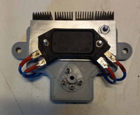
My new design has added considerable more surface area , thanks to 4 finned heat sinks , and addition of 1/8 piece of 90* aluminum. Also added spacers to lift the entire mount up to allow full airflow under it. Other tiny tweaks here and there.

Something else I learned that is unique to my specific setup is air flow. Most cars will have a large amount of of under hood air flow, thanks to the factory style mechanical fan. In my case though I am running dual electric fans. My setup is dual 12" fans housed in a completely sealed shroud to my rad. Although this does an excellent job of cooling the engine , it does not create much under hood air flow. Even when the fans are running , most air flow is directly towards the engine block. Again great at doing what its ment to do, but really cuts down on under hood air flow. Especially something mounted on the fire wall.

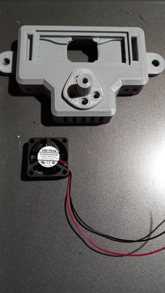
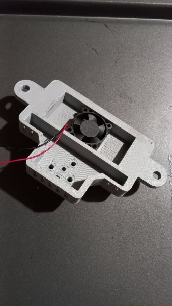
Trying to problem solve this for my set up, i was able to add a small 30mm fan inside my design . I created a duct system that send air flow over the entire backside of the heatsink. It's then direct up both sides and blows on the upper part of heat sink as well. The added air movement is key as it greatly improves the heat disappation. This design is slightly different from the original , as trying control the flow of air to and from the fan.

The little fan draws an almost unnoticeable .1 amp but moves about 4cfm of air . It's powered off the same wire that powers the module. No additional wiring needed.

I now have 2 designs .

1. Original design with upgraded heat sink which will be suitable for most cars.
2. Original design with added fan and duct work.

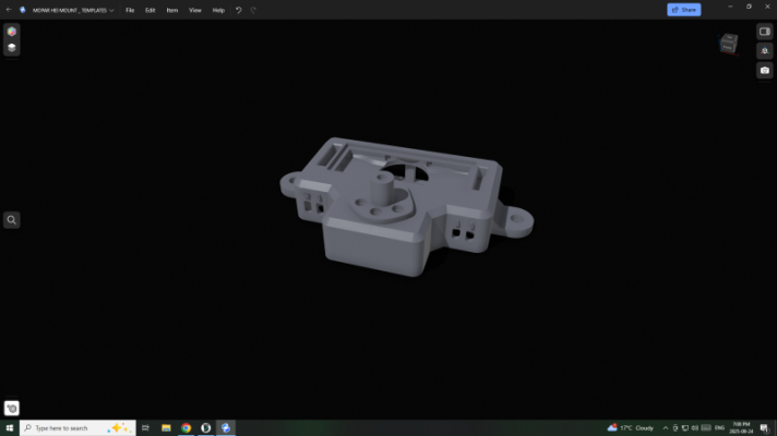
Some pictures of design without fan, as well as some proto type of fan design and 3D renderings.

Enjoy !


1000007676.jpg1000007675.jpg1000007674.jpg1000007678.jpg1000007679.jpgScreenshot (17).pngScreenshot (14).pngScreenshot (19).png
 
I like that you have the desire and curiosity to pursue this. SOME people might demand that we stick with points ignition but you are looking to make a better “mousetrap”.
Thank you.
 
How on earth did the HEI modules ever work for millions of miles inside of a sealed distributor in millions of GM vehicles?
Mike
 
How on earth did the HEI modules ever work for millions of miles inside of a sealed distributor in millions of GM vehicles?
Mike

Pretty sure the caps were not completely sealed they did have vent holes i belive ? ? I could be wrong on that ? But the distributor does act as a very large heat sink. Just like the design to drive mount you use, it's bolted to the distributor as well. ?
 
I like that you have the desire and curiosity to pursue this. SOME people might demand that we stick with points ignition but you are looking to make a better “mousetrap”.
Thank you.


Thanks , its just that . Curiosity, I just really enjoy the challenge and fabricating. I know you can do the swap a million different ways, and make it super simple. But I've always enjoyed "thinking outside the box "
 
Great things get discovered by people that dare to follow their curiosity. There are ******** that will tease or insult those that try different things but those people are just armchair quarterbacks that never had the imagination nor guts to try something new.
My ignition system in the red car is solid now but I may look you up for this. Who knows, maybe I'd make an across the board change to the 6 cars I have here.
 
Pretty sure the caps were not completely sealed they did have vent holes i belive ? ? I could be wrong on that ? But the distributor does act as a very large heat sink. Just like the design to drive mount you use, it's bolted to the distributor as well. ?
Not air tight sealed but I don’t think they have real venting that I can recall seeing, and a quick image search backs that up. Makes me wonder if the module in my 77 vette is a time bomb.
 
Can 1968.

Glad you are happy with your new set up but I think it is overkill.
The original GM HEI 5" cap had only a small opening for ' airflow' & that was around the vac adv opening. Many GM engines had rear mount engines. The HEI dist got very hot by conduction of heat [ direct heat transfer ] from the block into the dist.....& got hot air blown back by the fan & general trapped heat under the hood. Yet they survived.
 
Can 1968.

Glad you are happy with your new set up but I think it is overkill.
The original GM HEI 5" cap had only a small opening for ' airflow' & that was around the vac adv opening.***( Many GM engines had rear mount engines.)*** The HEI dist got very hot by conduction of heat [ direct heat transfer ] from the block into the dist.....& got hot air blown back by the fan & general trapped heat under the hood. Yet they survived.

I think you meant that many GM engines had rear mounted distributors. You mentioned this in this thread in May of this year.

Those modules survived being mounted on rear mounted dists on GM cars + the Arizona heat.

I do think the heat sink should be a little thicker 1/8-3/16" for peace of mind....
 
Kern,
Yes I meant rear mount dist.
Yes, 1/8-3/16" thick but does not need to be finned. Can just be scrap alum that you have on hand.
 
Can 1968.

Glad you are happy with your new set up but I think it is overkill.
The original GM HEI 5" cap had only a small opening for ' airflow' & that was around the vac adv opening. Many GM engines had rear mount engines. The HEI dist got very hot by conduction of heat [ direct heat transfer ] from the block into the dist.....& got hot air blown back by the fan & general trapped heat under the hood. Yet they survived.

Thanks, I would rather be on the side of overkill than not enough.
 
Auto Transport Service
Back
Top