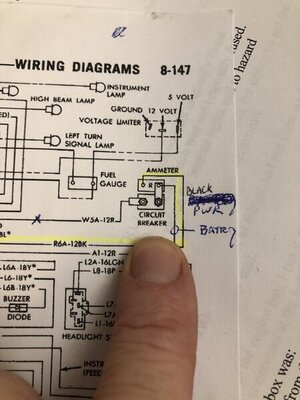
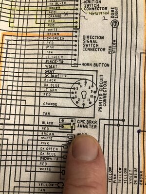
Seems like Black AND Red are used for Vbatt any rational reason why Chrysler did this? Black has traditionally been relegated for ground but in my 1970 Red and Black are Vbatt.
You are using an out of date browser. It may not display this or other websites correctly.
You should upgrade or use an alternative browser.
You should upgrade or use an alternative browser.
Battery Wire Color Convention
- Thread starter Moparfiend
- Start date
70chall440
Well-Known Member
- Local time
- 11:00 PM
- Joined
- Feb 11, 2018
- Messages
- 4,579
- Reaction score
- 6,344
- Location
- Yelm, Washington
May I ask what you mean "Vbatt"?
Sorry direct Battery Positive is often referred to as Vbat on electronic schematics.May I ask what you mean "Vbatt"?
- Local time
- 2:00 AM
- Joined
- Mar 10, 2010
- Messages
- 29,611
- Reaction score
- 51,173
- Location
- Hanover, Pennslyvania
Is it a red cable with a black stripe or black with a red stripe.

Well the schematic clearly shoes it go from the battery red cable to the blue fusible link to the bulkhead then red out of bulkhead to the ammeter. The other side ammeter”/circuit breaker” lol then Black. The all the colors that are hot like violet and yellow etc. Formally any live bat lines IMO should be red period. But Chrysler wanted to delineate certain battery line functions by color (like yellow and violet) but why mix Black and Red with Vbatt is beyond me.Is it a red cable with a black stripe or black with a red stripe.
Also by calling the Ammeter a “Crkt Brkr” which they do on the schematic in the FSM they must have intended it to be a fusible link. Not very bright given its location and lack of fire protection.
- Local time
- 11:00 PM
- Joined
- Jan 14, 2009
- Messages
- 1,937
- Reaction score
- 1,467
- Location
- Shoreline, Washington
A wire color convention? On old Mopars? There isn’t one. Black wires are used for grounds and positive voltages in various vehicle circuits. Wire color/tracing coding can change multiple times for different segments of the same circuit as well.
Its not much of a convention for Red Pos and Black Neg..... thats just common sense from my perspective but then again I am deranged....A wire color convention? On old Mopars? There isn’t one. Black wires are used for grounds and positive voltages in various vehicle circuits. Wire color/tracing coding can change multiple times for different segments of the same circuit as well.
- Local time
- 11:00 PM
- Joined
- Jan 14, 2009
- Messages
- 1,937
- Reaction score
- 1,467
- Location
- Shoreline, Washington
I think you are mis-interpreting that notation on page 8-147 of the ’70 FSM. I’ve never seen the ammeter referred to as anything but an ammeter in any of the factory diagrams from that time. If you look carefully, there is a self-resetting circuit breaker pictured mounted to an ammeter stub for a power tail gate window and/or power windows.Also by calling the Ammeter a “Crkt Brkr” which they do on the schematic in the FSM they must have intended it to be a fusible link. Not very bright given its location and lack of fire protection.
I know I have sexy fingers....I think you are mis-interpreting that notation on page 8-147 of the ’70 FSM. I’ve never seen the ammeter referred to as anything but an ammeter in any of the factory diagrams from that time. If you look carefully, there is a self-resetting circuit breaker pictured mounted to an ammeter stub for a power tail gate window and/or power windows.


- Local time
- 11:00 PM
- Joined
- Jan 14, 2009
- Messages
- 1,937
- Reaction score
- 1,467
- Location
- Shoreline, Washington
And? I see ammeters with an optional power windows circuit breaker if so equipped. Follow W5A-12R to the optional circuit components. I don’t see the ammeter labeled as a circuit breaker. Sedan, no power windows, the circuit breaker will not be there.
It looks like a single symbol in both elements are hooked up but that’s OK my point is is that the color coding really is screwy and apparently the symbols are as well in my opinion but that was 50 years ago so who knows conventions were differentAnd? I see ammeters with an optional power windows circuit breaker if so equipped. Follow W5A-12R to the optional circuit components. I don’t see the ammeter labeled as a circuit breaker. Sedan, no power windows, the circuit breaker will not be there.
- Local time
- 11:00 PM
- Joined
- Jan 14, 2009
- Messages
- 1,937
- Reaction score
- 1,467
- Location
- Shoreline, Washington
I agree the third-party diagram labeling is not clear at all and shows no load connected to the circuit breaker, that’s why those diagrams are worthless. The factory diagram labeling is clear even if the color coding from that time is confusing by today’s standards.
Similar threads
- Replies
- 10
- Views
- 757
- Replies
- 9
- Views
- 2K


