• When you click on links to various merchants on this site and make a purchase, this can result in this site earning a commission. Affiliate programs and affiliations include, but are not limited to, the eBay Partner Network.

Charging Mystery - 69 GTX

If you use that regulator your gonna be dicing and splicing your wiring! Verify the wiring that is in there now. More than likely it is set up for the later style alternator. If that is the case you should just get the correct alternator and put your current one up for sale here.
 
If you use that regulator your gonna be dicing and splicing your wiring! Verify the wiring that is in there now. More than likely it is set up for the later style alternator. If that is the case you should just get the correct alternator and put your current one up for sale here.
The other advantage is the new style (2 field connections) puts out more amperage at lower RPM.
IE your lights don't dim as much at a stoplight.
 
If you use that regulator your gonna be dicing and splicing your wiring! Verify the wiring that is in there now. More than likely it is set up for the later style alternator. If that is the case you should just get the correct alternator and put your current one up for sale here.

OK that's why I asked if the second field terminal on the 2 field terminal alternator goes to ground on the alternator case. Because the 70 regulator only has two pins and the harness plug only has two wires. You say "verify the wiring" its basically 12V in on blue and (apparently) variable ground on green.
 
QUOTE="ToddMcF2002, post: 912062202, member: 37637"]OK that's why I asked if the second field terminal on the 2 field terminal alternator goes to ground on the alternator case. Because the 70 regulator only has two pins and the harness plug only has two wires. You say "verify the wiring" its basically 12V in on blue and (apparently) variable ground on green.[/QUOTE]
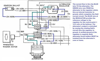
What I mean by verify the wiring is to check if there are a blue and a green wire by the alternator for the field circuit. That would show that it's set up for the later style alternator.
 
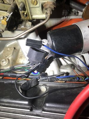
In pic 2 I can see the harness towards the top that has a green, blue and a black wire with tracer. Where does the blue wire go? That is probably the second field wire.
 
Here is the one I've ordered. I'm assuming I'll see some kind of voltage on the FLD terminal when voltage on IGN is less than ~14.5 volts

View attachment 1191761
View attachment 1191762
This style of regulator is used on the PRE 1970 (1969 and earlier) single brush alternators rotating field connections. Full battery voltage is applied to the IGN (ignition) terminal at ignition turn on. Without the engine running, full battery voltage will appear at the FLD (field) terminal as well. After the engine is started and system (battery) voltage has stabilized, and is starting to rise to the control point, ~14.5 volts, the intetnal relay will be energized, causing the resistor connected between the IGN and FLD, to reduce the alternator's field voltage, limiting the alternator's output. IF, during light load conditions, with very little accessories are on, and high speed operation, the voltage regulator will DISCONNECT the field voltage, turning off the alternator's output. The system will cycle between full voltage, reduced voltage and no voltage applied to the alternator's field to limit the voltage to a nominal ~14.5 output. Sort of a MECHANICAL pulse width modulated system.
Paraphrased from the Factory Service Manual.....
BOB RENTON
 
Thanks Bob that is super clear and the behavior I thought I was going to see in the 70 regulator. I'll run this 69 regulator without cutting any wiring until I figure out the harness. I suspect Rockland71GTX is correct. The whole harness is new and if it has a 70 regulator pigtail its likely setup for 70 as suggested.
 
In pic 2 I can see the harness towards the top that has a green, blue and a black wire with tracer. Where does the blue wire go? That is probably the second field wire.

And that blue wire should have 12V on it FLD(+) because its sliced into from the ballast resistor between the Regulator and Alternator correct?

70_alt_reg_wiring.jpg
 
And that blue wire should have 12V on it FLD(+) because its sliced into from the ballast resistor between the Regulator and Alternator correct?

View attachment 1191881
To continue this discussion.....FYI, there are after market ELECTRONIC Voltage regulators available that physically resemble the ECHLIN mechanical regulator you show in pix #20. The aftermarket version has a transistor that provides the variable field voltage to the alternator......seamlessly. The mechanical regulator has internal contact points that does the voltage switching, but is subject wear, arcing and possible failures and inaccuracies. The aftermarket unit operates without moving contacts and is far more accurate....the cost is approximately $ 25-30. Google it or perhaps someone can supply a link for you to see for yourself. It completely interchanges with the mechanical regulator in both appearance, wiring, and mounting. Just something else to consider.......
BOB RENTON
 
YES! Follow that diagram and see that you have the 2 field wires by the alternator. If you do then just get the correct alternator rather than rewire your car for the alternator you have now.
 
YES! Follow that diagram and see that you have the 2 field wires by the alternator. If you do then just get the correct alternator rather than rewire your car for the alternator you have now.

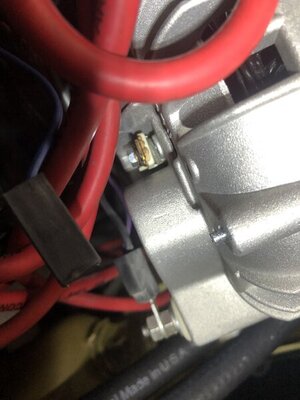
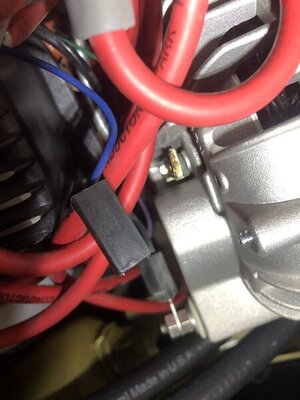
yup it appears I’m buying a 70+ two field alternator. This wire has 12V with ignition in “run”. My other field wire is still attached to the old alternator.

9592BF7A-B6A8-4541-87E8-0CF2F660D562.jpeg
 
Ok this car is kicking my butt. New (2) FLD alternator. FLD terminal immediately started smoking when it saw power. I caught it fast no damage. Any ideas? Case appears to be grounded

C4552CB3-D61C-4D7E-A621-9F4FD981682A.jpeg A47EAB45-3F27-411B-A6E8-F5329D20003F.jpeg
 
Ok this car is kicking my butt. New (2) FLD alternator. FLD terminal immediately started smoking when it saw power. I caught it fast no damage. Any ideas? Case appears to be grounded

View attachment 1192136 View attachment 1192137

IMO....
Apparently, the auto parts store supplied an alternator with one of the two field brushes grounded (the one you noticed smoking). This alternator could be used on the single field wire system. To use this alternator on a two field wire installation, one of the two brush holders must be ungrounded (either one, it matters not), allowing the use of the 1970 and newer style alternator. Most rebuilders do this to achieve a more universal coverage but fail to notify the purchaser of this aspect and you (the purchaser) are unaware of the change and this results in wiring damage issues. The fix.....change the grounded brush holder, making sure the mounting screw does not ground the terminal to the case. Remove the alternator and examine both brush holders to insure that neither is grounded to the case. Just my opinion of course....
BOB RENTON
 
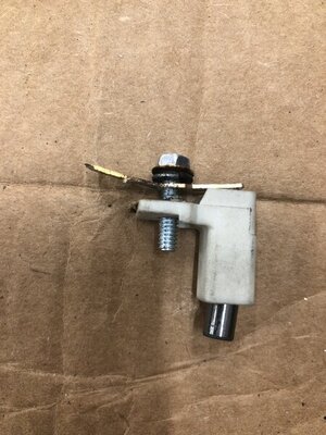
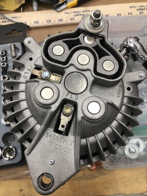
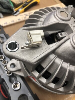
Thanks Bob - may need a bit more help with that one. This is the unit. I pulled the terminals (brushes on springs?) they seem ok. The one that smoked (12V) points to the face of the hub the one running the green wire face inwards. They both have little rubber isolators in them. Not clear how to approach this?

70F9A20B-104B-4F8C-9927-4A90F9F40DD9.jpeg E61FE26F-2FA2-441B-944C-FB31D6382ADE.jpeg BD6832EC-7057-403F-93D3-C6D5FED7B76D.jpeg
 
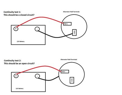
I really hate just throwing money at a problem. I don't understand how I can isolate these terminals from the case given the screws screw into the case. I can't believe I'm still stuck on this. Is there a way I can devise a continuity test from the bench? Would this validate the alternator FLD/case grounding?

alt_test.jpg
 
Thanks Bob - may need a bit more help with that one. This is the unit. I pulled the terminals (brushes on springs?) they seem ok. The one that smoked (12V) points to the face of the hub the one running the green wire face inwards. They both have little rubber isolators in them. Not clear how to approach this?

View attachment 1192152 View attachment 1192155 View attachment 1192156

The units I've seen, have an insulating washer under the head of the mounting screw AND an insulating sleeve on the screw threads, on both brush holders. YES....both brushes are on springs to maintain pressure on the rotor's slip ring contacts.
When the brush holders and brushes are assembled to the case, the holders and connecting terminals are INSULATED from the case mounting screws. To satisfy the connection is insulated, using an digital ohm meter, set at Rx1 scale, measure the resistance from the terminal to the case of each assembly. There must be infinity reading or open circuit or no resistance to the case. It is possible that there is a ground connection or low resistance connection at the rotor's slip ring assembly, to the rotor's internal mounting or windings. If this is the case, it should be a warranty issue.
Examine each brush holder to insure its not cracked or damaged. Insure that each insulating washer under the head and insulating sleeve is intact and not split. Both brush holders and their respective mounting hardware MUST be insulated from the case mounting screws. Hope this helps answer your questions......
BOB RENTON
 
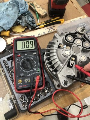
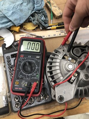
I don’t know if I’m doing something wrong here but this alternator seems to have both terminals grounded to the case. Assuming the isolators are isolating then something internal is grounding to the case?

2142A487-5A3C-435D-92E4-A82E439A580B.jpeg 304282DE-F3A4-4824-915B-B50D235C2B7C.jpeg
 
I don’t know if I’m doing something wrong here but this alternator seems to have both terminals grounded to the case. Assuming the isolators are isolating then something internal is grounding to the case?

View attachment 1192217 View attachment 1192218

IMO.....you are checking correctly. As previously mentioned, it may be possible that the rotor is grounded internally, at the slip ring assembly (the part that the brushes contact and rotates). You might try removing one brush holder assembly then performing the resistance test on the remaining brush holder assembly to try and isolate which brush holder assembly may be grounded.
If you cannot isolate which brush holder(s) may be defective, return the unit to the place of purchase and explain your circumstances. And request they test it or exchange It for a tested unit (by them), maintaining that BOTH field connection MUST BE ISOLATED (NOT GROUNDED) FROM THE CASE. Just my opinion......
BOB RENTON

I'll try that before I return it for education purposes if nothing else. Its going back - I ordered a PowerMaster 7019. I don't see how the unit isn't defective. There is no way to get it wrong correct? The field wires are supposted to interchangeable anyway and besides mounting it the only other connection is the output. There is literally no way to install this thing incorrectly and the car is only providing 12.5V right now. It smoked as soon as the ballast sent power - before I even tried to start it.
 
Auto Transport Service
Back
Top