• When you click on links to various merchants on this site and make a purchase, this can result in this site earning a commission. Affiliate programs and affiliations include, but are not limited to, the eBay Partner Network.

Hawk-Rod: The Restoration

I don't know if mine are original paint but they look more orange or orangy/red? and they absolutely look like it was done with a brush. I repainted mine black, just cause I couldn't stand the look of the orange showing through the mags...

Been there on the "do it fast and regret it" front...
 
Something like this, if you really want to change it i would use regular paint stripper, nice an thick and i cant see why it would hurt and it would take it off in short order, clean it up real good and back to ready for paint! Don't judge yourself to hard, i could start a 10 page thread on my not thinking straight and just getting in a hurry to finish things, and no, ill pass on really doing it, when i think of them i get mad! lol.
Come on Ron, you could start a thread and ask everyone to share they're idiot moments (I've got more than my share haha).
 
This might help also, here is how the factory painted them (note # 6).
From what I know, the red was done with a brush and usually not very well done either.

That is a great piece of information - thanks! So here I was painting them all red, when I should really just paint part of them red. Oh well, so much for factory correctness! The good news is I can readily replicate the crappy factory job!!! Now THAT is easy for me! :icon_tongue:

In other news, I shipped out my gauges to get them rescreened. I am behind doing that, as it will take 8-10 weeks. Yikes. That will make it difficult since I need to get the dash in relatively soon. Once the body is in primer and cut in, the car will get its wheels back and become a roller. Soon after that, the fully completed dash will go back in so then the windshield can be replaced as well. Not sure if I will get the final paint done before or after the dash - we'll see how the timing works out...

We are on the return path! It's always cool when parts start going back ON the car!
 
Come on Ron, you could start a thread and ask everyone to share they're idiot moments (I've got more than my share haha).

Lol, If i did that i probably would run out of ink telling my tales of Idiotic moves! :)

- - - Updated - - -

Ask my wife! ROFL...
 
Lol, If i did that i probably would run out of ink telling my tales of Idiotic moves! :)

- - - Updated - - -

Ask my wife! ROFL...

AHEM... I have never screwed up :angel9:

(smile) At least not today - yet...................
 
AHEM... I have never screwed up :angel9:

(smile) At least not today - yet...................

LOL, Well, im not sure i can claim the same! ill have to ask my wife...... Ok, i cant claim the same, something about i got up this AM! ROFL.. Im glad her and i can joke together, it sure makes life a whole lot better! :)
 
Stage II box and Sector Support

So I got some more work done today.

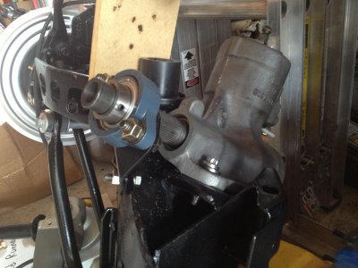
Last week I got my stage II box from Firm Feel. I also ordered a sector support kit that helps keep deflection at a minimum from the steering shaft/pitman arm. Some shots of me mocking it up on my K-Member...

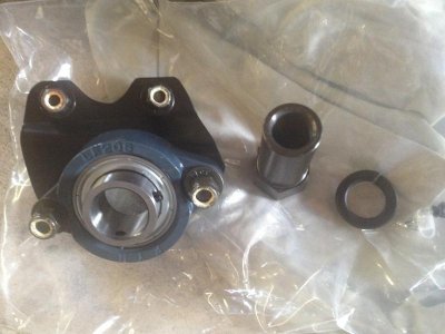
So this is the sector support kit...
IMG_2531.jpg

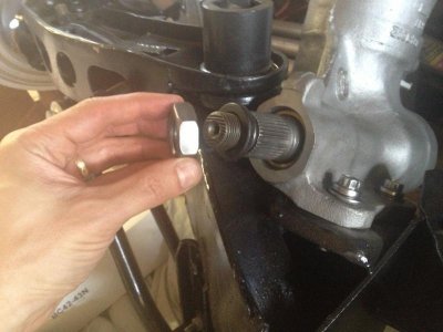
First, you remove the standard nut (in this picture, my pitman arm is not attached).
IMG_2533.jpg

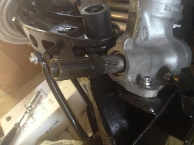
Then you put this long neck nut on instead.
IMG_2535.jpg

A bearing system slides over that head. The bearing bolts to the lip of the K-Member, stiffening up the end of the pitman arm where there is deflection during turning. (Note: This is just mocked up, as I used other nuts rather than the lock nuts to check fit.)
IMG_2538.jpg
IMG_2539.jpg

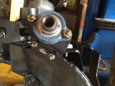
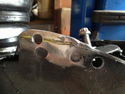
Now in my case, installation was not so easy. The bearing bracket did not want to line up with the lip of the K-Member very well. One bolt hole was off, no matter how I tried to adjust it (the bearing rotates in the assembly a little bit). So I ground off the paint and added weld to the edge of the K-Member to build it up. The line in the picture below roughly shows where the original edge of the K-Member was. Once I got the material added, I drilled the holes and it fit great. Then it all came off so I could paint the steering box (cast look) and touch up the K-Member...
IMG_2540.jpg

IMG_2531.jpg IMG_2533.jpg IMG_2535.jpg IMG_2538.jpg IMG_2539.jpg IMG_2540.jpg
 
Last edited:
So I got some more work done today.

Last week I got my stage II box from Firm Feel. I also ordered a sector support kit that helps keep deflection at a minimum from the steering shaft/pitman arm. Some shots of me mocking it up on my K-Member...

So this is the sector support kit...
View attachment 196288

First, you remove the standard nut (in this picture, my pitman arm is not attached).
View attachment 196289

Then you put this long neck nut on instead.
View attachment 196290

A bearing system slides over that head. The bearing bolts to the lip of the K-Member, stiffening up the end of the pitman arm where there is deflection during turning. (Note: This is just mocked up, as I used other nuts rather than the lock nuts to check fit.)
View attachment 196291
View attachment 196292

Now in may case, installation was not so easy. The bearing bracket did not want to line up with the lip of the K-Member very well. One bolt hole was off, no matter how I tried to adjust it (the bearing rotates in the assembly a little bit). So I ground off the paint and added weld to the edge of the K-Member to build it up. The line in the picture below roughly shows where the original edge of the K-Member was. Once I got the material added, I drilled the holes and it fit great. Then it all came off so I could paint the steering box (cast look) and touch up the K-Member...
View attachment 196293

I've been thinking about doing that down the road and it sounded so easy in Ebooger's how to article. Thanks for the pics and tech Hawk
 
On "The Cradle"

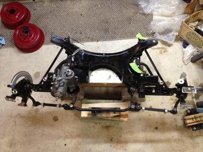
So I also built my REALLY LOW TECH cradle today. I am almost ashamed to show it due to all of the really nice cradles that others have developed, but I had little time and limited materials so I used what I had on hand. (That's my excuse and I'm sticking with it... :icon_fU: )

The main support is a 6x6 beam. I attached that to two carpeted rectangular frames that I made for my wheel
"skates", and they are attached to the skates. On top of the 6x6 I have another board with two very large bolts through it. They are sized so that they fit into two holes that are in the K-Member. The K-Member sits on that assembly. Everything is attached together, although only the weight of the K-Member hold it to the wooden cradle.

I installed my Firm Feel Stage II steering box and all connected the sector support. Here is what the whole contraption looks like at this point:
IMG_2547.jpg

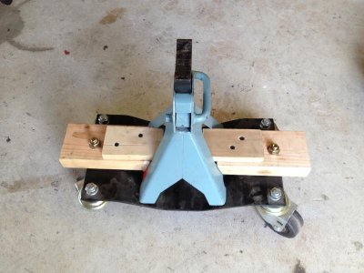
Once the engine and transmission assembly get attached, this contraption will hold up the back. It is another wheel skate with a jack stand on it. I cut some 2x4s with the correct angle and then bolted them to the skate. They hold the jack stand in place. Finally, two small boards screwed on top of those to keep the jack stands from sliding out side to side. Yes, it's low tech, but it should hold up the tranny OK and the whole thing should be able to move around...
IMG_2542.jpg

- - - Updated - - -

I've been thinking about doing that down the road and it sounded so easy in Ebooger's how to article. Thanks for the pics and tech Hawk

Every K-Member is probably a bit different. I would think that most fit right away and bolt up. Not sure what the deal was with mine, but it is what it is...

Just goes to show that sometimes things aren't as easy as you think. I figured it would be quick - so much for my estimate!!!
 
Sector support??????????????? This is all news to me, do they actually move that much? Seems like they would be really rigid as is but what do I know. Looking good
 
Sector support??????????????? This is all news to me, do they actually move that much? Seems like they would be really rigid as is but what do I know. Looking good

Yes! They do move quite a bit. I have the support for my GTX but have been waiting for other things to come together so I can put it on. I think I will have to add some material to my k member too.

Thanks for those pics Hawk. BTW that cradle is fine, heck use a skateboard from Walmart as long as it doesn't collapse!

-Mark

PS if I can get organized I will mount a gopro under the car and shoot some video of the steering under load. It is pretty interesting the movement you get throwing a 3800lb pig into a cloverleaf at a high rate of speed!

LOL. I actually DID use my old skateboard in "the old days" when I pulled my tranny...
 
Yes! They do move quite a bit. I have the support for my GTX but have been waiting for other things to come together so I can put it on. I think I will have to add some material to my k member too.

Thanks for those pics Hawk. BTW that cradle is fine, heck use a skateboard from Walmart as long as it doesn't collapse!

-Mark

PS if I can get organized I will mount a gopro under the car and shoot some video of the steering under load. It is pretty interesting the movement you get throwing a 3800lb pig into a cloverleaf at a high rate of speed!
That would be pretty cool to see.
 
I spent the 4th of July working on a great American car. What could be a better way to celebrate?

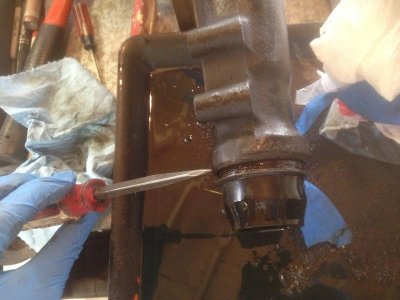
I did a lot of cleaning and other tasks, but nothing too exciting from a picture perspective. First, I replaced the rear seal on my transmission. First, to get the old one out. I used an old sharpened screwdriver to gently tap it between the seal and transmission and create a gap. This made it pretty easy to get out:
IMG_2549.jpg

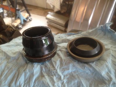
The old and new seal. The new seal is obviously different, but if it works OK, that's fine by me...
IMG_2550.jpg

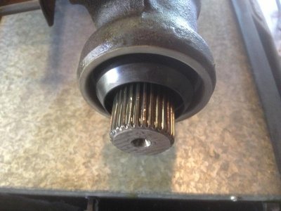
New seal installed.
IMG_2579.jpg

I also started disassembling and cleaning up my shifter, but those can be some pictures for another post. I also took off my oil pan from my engine to get a dent out of it. I'll post some pictures of the engine too once it starts getting cleaned up.
 
So I spent some time with the engine. It is a 383 that I believe has around 80,000 original miles. I doesn't look like the engine has ever had the heads taken off the car. Anyway, the budget will not currently allow for the engine to be rebuilt, so that will need to be a project for another year.

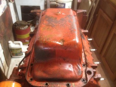
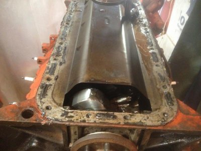
So with that in mind, I set to clean it up and get it ready to go back in the car. My oil pan had a dent in it that I thought I should take out, so I took it off, mostly removed the dent (hard because the darn thing is baffled), and replaced it. Here is the dent:
IMG_2571.jpg

Here is the windage tray from a HP 383.
IMG_2570.jpg

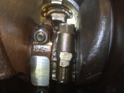
Looks like the rods were marked. Here is #4 as an example. Did Ma Mopar do that when they built the engines, or does that mean the rods have been out?
IMG_2585.jpg

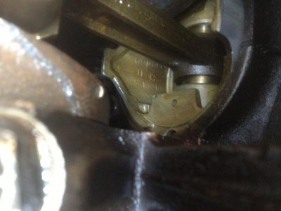
Here is a view of the inside of one of the pistons.
IMG_2586.jpg

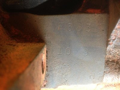
My engine pad.
IMG_2591.jpg

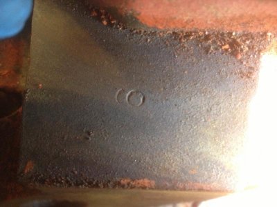
This is on the opposite side from the distributor. Anyone know what this symbol means? Is it a "6"?
IMG_2597.jpg

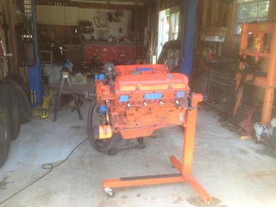
Engine during prepping and cleaning
IMG_2599.jpg

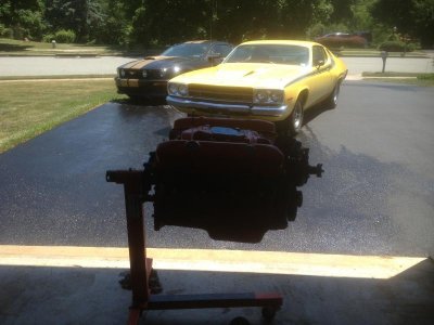
OK, I tried to get creative - so shoot me! Here is the engine with my son's Road Runner (my first car) and my daughter's Mustang.
IMG_2600.jpg

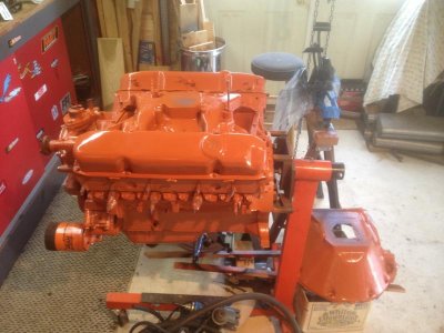
The finished product. Mind you, the paint is rough because it is hard to get a complete engine really clean, but it should hopefully do for a year or two before it come out for a rebuild. Now to let the paint set for a day or two and then it will be time to start mounting parts back on it...
IMG_2603.jpg
 
So I spent some time with the engine. It is a 383 that I believe has around 80,000 original miles. I doesn't look like the engine has ever had the heads taken off the car. Anyway, the budget will not currently allow for the engine to be rebuilt, so that will need to be a project for another year.

So with that in mind, I set to clean it up and get it ready to go back in the car. My oil pan had a dent in it that I thought I should take out, so I took it off, mostly removed the dent (hard because the darn thing is baffled), and replaced it. Here is the dent:
View attachment 197551

Here is the windage tray from a HP 383.
View attachment 197552

Looks like the rods were marked. Here is #4 as an example. Did Ma Mopar do that when they built the engines, or does that mean the rods have been out?
View attachment 197553

Here is a view of the inside of one of the pistons.
View attachment 197554

My engine pad.
View attachment 197555

This is on the opposite side from the distributor. Anyone know what this symbol means? Is it a "6"?
View attachment 197556

Engine during prepping and cleaning
View attachment 197557

OK, I tried to get creative - so shoot me! Here is the engine with my son's Road Runner (my first car) and my daughter's Mustang.
View attachment 197558

The finished product. Mind you, the paint is rough because it is hard to get a complete engine really clean, but it should hopefully do for a year or two before it come out for a rebuild. Now to let the paint set for a day or two and then it will be time to start mounting parts back on it...
View attachment 197559
Looking really good. Can't wait to see it with the fuel injection.
 
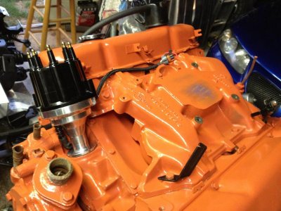
So I installed the FAST distributor on the engine. It wasn't as easy as I expected (what else is new), but I am glad the I trial fitted the thing before I got too far.

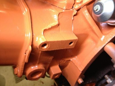
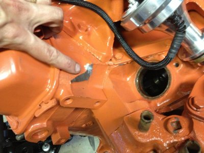
It turns out my head needed some clearancing before the extra big GM cap would fit. Grinding makes a heck of a mess, and keeping the shavings out of the engine is easy now with everything securely taped up (and yes, I did carefully re-tape the distributor hole when I ground)

Here is the finished installation:
IMG_2620.jpg

This is the back of the other head, just to show the "ridge" that had to be ground off.
IMG_2619.jpg

This is the head after grinding - I didn't have to grind a lot, but that small amount was crucial to getting it to fit properly and turn without hitting the head...
IMG_2618.jpg
 
Auto Transport Service
Back
Top