• When you click on links to various merchants on this site and make a purchase, this can result in this site earning a commission. Affiliate programs and affiliations include, but are not limited to, the eBay Partner Network.

605" Street Hemi Build.

Actually, Blaine is just southwest of me. I'm in North Branch.

In '94 I bought a '90 dodge 1/2T pickup that was from North Branch, maybe it was yours? ha ha ha
Impressive work your doing up there, look forward to your new posts.
 
Not much dome on those pistons to get in the way of flame travel. I suppose that's what happens when dealing with 605". You sure have the equipment and I can't wait for the tour. Last I checked BHJ is in Union City CA, which is about 20 mins from my work. They have a block align boring jig that also does the cam bore.

And speaking of that, do you notice that cams never seem to fit properly even with new bearings? Sure, popping in a set of cam bearings and making sure the cam doesn't bind will work, but the factory spec for most cam bearing clearance hovers about .001" or less. And you can't get there unless you install undersize bearings and align hone them. I can only reason this out based on my experience as a mech tech but never did any automotive machine work. How do you deal with this issue? Back to that BHJ fixture?

I have not had too many problems with cam bearings. On some if the bores are a bit tight, you cam polish the OD of the bearing down to get the press fit back to where it should be. This brings the clearance right in.
I have had to bore cam bearing bores for oversize bearings too. On aluminum blocks, you need the crush on the tight side. If the cam journal itself is on the large side though, we send the cam out and have the journals ground to the low limit.
My line boring machine will bore some of the bigger cam bores.

You just need to treat cam bearings like crank bearings. Adjust where required, however you need to.
 
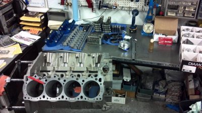
Assembly has finally begun.

Notice the T wrench in the oil feed for the top end. On the Mopar Performance block, this is threaded and has the restrictors screwed in. The MP block feeds top end oil from the lifter circuit, not the cam bearing. For this reason, the cam does not need a groove.

I will not be using the restrictors at this location.... I machine the rocker stands for the restrictors. This does a couple things.
First; if I want to add or reduce the amount of top end oil, I only need to pull the shafts forward and remove the one stand on each side, not the whole head.

Second; I can adjust the amount of oil to the intake and exhaust shafts individually by changing the restrictor oriface size.

Because of the situation with the hydraulic roller lifters height differences and the lack of a bushed type roller wheel, we have decided on a solid roller. It will be a custom grind, and we will use the Isky EZ roll Max lifters.

So , more on the cam later. I have some ideas that have worked well on my Chevy engines. Low lift, high duration grinds that performed great.

image.jpg
 
I was recently talking to a buddy who wants to make a similar oiling mod to a wedge block. Not something what I was expecting, but he said some roller rockers need a lot of oil to keep happy. So eliminating the duty cycle oiling through the cam and cross drilling the passage into the main lifter feed was a way to get oil 100% of the time. I would definitely like to learn more about this mod.
 
I was recently talking to a buddy who wants to make a similar oiling mod to a wedge block. Not something what I was expecting, but he said some roller rockers need a lot of oil to keep happy. So eliminating the duty cycle oiling through the cam and cross drilling the passage into the main lifter feed was a way to get oil 100% of the time. I would definitely like to learn more about this mod.

Your friend is right. I've seen problems with some roller rockers without needle bearings or bushings. Most of the time, I machine a groove in the 4th cam journal. This makes it oil 100%. A .050" wide by .020" deep groove does the job.

Doing it with simple lines from the deck/head feed galley to the lifter circuit works nice too. I use hard brake line and fittings.

On some aftermarket heads, like Indy, they use external oil lines to the rear two galley holes below the deck, but above the bell housing.

I built a B1 head engine using an Indy aluminum Hemi block once. (Before the wedge came out). The block conversion was a total pita. I used a jumper line between the two oil passengers in the valley. I machined the heads, under the rocker stands for NOS jets as restrictors.

Ford FE engines are the easiest. You just drop a Holley main jet right in the oil passage on on rocker pedestal under the shaft. If mopars were that easy...
 
Your friend is right. I've seen problems with some roller rockers without needle bearings or bushings. Most of the time, I machine a groove in the 4th cam journal. This makes it oil 100%. A .050" wide by .020" deep groove does the job.

Doing it with simple lines from the deck/head feed galley to the lifter circuit works nice too. I use hard brake line and fittings.
So you just drill and tap the top end feed galley and turn the cam bearing up side down to block the top end oiling holes? Then drill a new cam journal oiling hole from the main passage. On the other end you just eyeball a location (and hope you drill into the main lifter galley) then just connect with steel brake line?

On some aftermarket heads, like Indy, they use external oil lines to the rear two galley holes below the deck, but above the bell housing.
That would probably be where the oil pressure sender sits. A simple tee with a line to each head, however, you will need to drill into the rear rocker pedestal bolt hole and I guess plug the passage at the stock location.

I built a B1 head engine using an Indy aluminum Hemi block once. (Before the wedge came out). The block conversion was a total pita. I used a jumper line between the two oil passengers in the valley. I machined the heads, under the rocker stands for NOS jets as restrictors.

Ford FE engines are the easiest. You just drop a Holley main jet right in the oil passage on on rocker pedestal under the shaft. If mopars were that easy...

If I recall the FE top end gets 100% oil from behind the cam bearing (groove in block) so putting the Holley jet in the rocker shaft feed is to reduce the oil flow to the rockers. So the stock MoPar top end oiling method would seem to be ideal for the FE.

To me it seems that drastically increasing the oil volume to the top end better be met with very precise rocker pivot bushing to shaft clearances. Each rocker should leak the same amount of oil and the sum of all rockers hopefully is not enough to disturb what happens in the rest of the engine. Or if it you think it would get a high volume pump. Thinking about the stock oiling system more I bet the #4 main is not getting constant oil flow like the others. When that oil passage in the cam lines up to oil the rocker shaft there must be a pressure drop for a split second but I'm sure it's not enough to worry about.

To get 100% oiling to the top, yes, run a feed hole right into the lifter galley and into the circuit to feed the top. It's pretty simple to eyeball the hole. You couple even "T" it and run a jumper from one side to the other. You can use any number of ways to restrict it. A NOS jet and fitting, or set screw with a hole. You can block the cam to deck feed by tapping the feed hole down the deck under your new feed location and plugging it with a set screw.

I just like the idea of being able to adjust the amout of oil to the top without ripping into the whole engine.
 
I was recently talking to a buddy who wants to make a similar oiling mod to a wedge block. Not something what I was expecting, but he said some roller rockers need a lot of oil to keep happy. So eliminating the duty cycle oiling through the cam and cross drilling the passage into the main lifter feed was a way to get oil 100% of the time. I would definitely like to learn more about this mod.
I used the thread in restrictor method on my RB Wedge build... I haven't noticed any excessive roller rocker wear, but will keep my eyes on it!
I only used them because my block was already machined "Threaded" for them sometime prior to me owning it..
 
Gathering parts for new short block (500 c.i.) So subscribed to this thread.
 
I used the thread in restrictor method on my RB Wedge build... I haven't noticed any excessive roller rocker wear, but will keep my eyes on it!
I only used them because my block was already machined "Threaded" for them sometime prior to me owning it..

I had a friend who had built one with Comp roller rockers and a relative stout cam. It kept bluing and galling rockers. He tried a few things, including honing them to like .005" clearance (per Comp's instruction) before finally changing to a Harland Sharp roller.

I have use Koeffels aluminum rockers on B1 heads with .050" restrictors with no problems... It's odd how some engines have different requirements that others eve is they are much the same build.

The nice thing with a solid valve train is that you know in a hurry if something is amiss.
 
What's up with the t 400 and not a TF????

Well, he is running a Gear Vendors overdrive behind it and with a TF, they get really long.
The cost of building and converting a 4L80 or an A518 with all the right parts to handle the torque, is actually more expensive.

A 400 with straight cut gears and good hard parts will be tough as nails. The overdrive unit will make it a little more manageable on the highway.
 
Finally back on track with this project as some parts are rolling in. I decided to go with the standard height ext. ports as they are well up to the job.

I have posted some pictures of the Stage V head compared to the OEM Hemi head on my FB page. I have not measured the port differences in volume yet, but lets just say they are big, and have plenty of material to go bigger.

The porting on the guide boss areas is next, then I will install guides and finish the seats and the rest of the port work.

- - - Updated - - -

Pictures from my phone, sorry for the lighting....or lack thereof.

Wow that's HUGE. For the street? That's gonna be one insanely fun ride. I wan ryd?
 
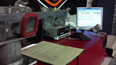
Initial flow figures on the heads.
2.3" intake 1.9" exhaust
Custom 4 angle intake and radius exhaust.

No burn through on the intake ports, but there was slight deflection on 4 of them. I will be installing tubes

Lift Intake Exhaust
-------------------------------
.200" 152 127
.300" 237 196
.400" 320 247
.500" 382 286
.600" 410 299
.650" 414 302

Tested on a Superflow 600 bench.
 
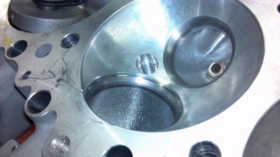
Finish touching up seat angles with fine stone. image.jpg

Final flow testing after an adjustment
image.jpg

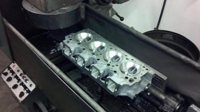
Resurfacing for MLS gasket. Just need to final volume check and assemble.
image.jpg
 
Hey, is that valve job NHRA legal? :tongueflap:
 
Very impressive work.

I look at that chamber and wonder if twin plugs would benefit this build. Even with the small dome piston, the bore size being pretty large may like the twin plug.
 
Auto Transport Service
Back
Top